Mitsubishi Outlander XL. Manual - part 308
ZK603636 AA00
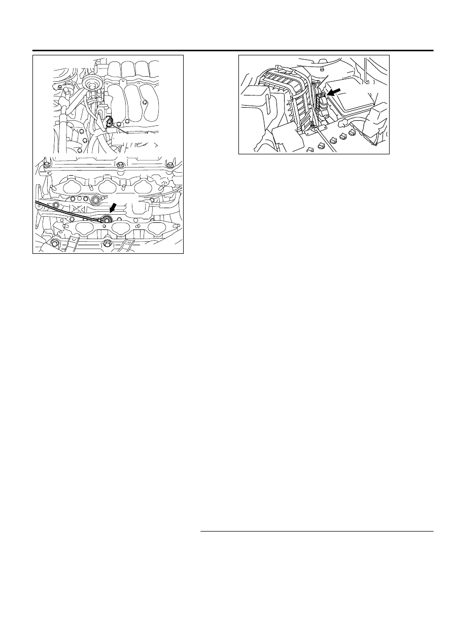
Knock sensor 2
B-20 (B)
Connector: B-20
ZK603591
ECM
B-10 (GR)
Connector: B-10
AA00
CIRCUIT OPERATION
⦆
The knock sensor (terminal No. 1) sends a signal
voltage to the ECM (terminal No. 28).
⦆
The ground terminal (terminal No. 2) is grounded
with ECM (terminal No. 29).
TECHNICAL DESCRIPTION
⦆
The ECM applies 5 V from the ground terminal side
to judge a malfunction in the knock sensor circuit.
⦆
The ECM judges whether the knock sensor signal
circuit has a short circuit to the ground or an open
circuit by checking the input voltage from the knock
sensor.
⦆
When the knock sensor output voltage is below the
reference voltage, it is judged that a malfunction
exists.
DTC SET CONDITIONS
Check Condition
⦆
2 seconds or more have passed since the engine
starting sequence was completed.
Judgement Criterion
⦆
Knock sensor 2 output voltage has continued to be
lower than 0.5 volt for 2 seconds.
TROUBLESHOOTING HINTS (The most likely
causes for this code to be set are:)
⦆
Knock sensor 2 failed.
⦆
Harness damage.
⦆
Connector damage.
⦆
ECM failed.
DIAGNOSIS
Required Special Tools:
⦆
MB991958: Scan Tool (M.U.T.-III Sub Assembly)
⦆
MB991824: V.C.I.
⦆
MB991827: USB Cable
⦆
MB991910: Main Harness A
STEP 1. Check harness connector B-20 at the knock sensor
2 and harness connector B-10 at ECM for damage.
Q:Is the harness connector in good condition?
MULTIPORT INJECTION SYSTEM (MFI) <DIAGNOSIS>
13Ab-427
DIAGNOSTIC TROUBLE CODE PROCEDURES