Mitsubishi Outlander XL. Manual - part 307


  Index      Mitsubishi     Mitsubishi Outlander XL - service repair manual 2007 year


Search            


Content   ..  305  306  307  308   ..


Mitsubishi Outlander XL. Manual - part 307


Q:Is DTC P0328 set?

YES:

 Retry the troubleshooting.

NO:

 The inspection is complete.

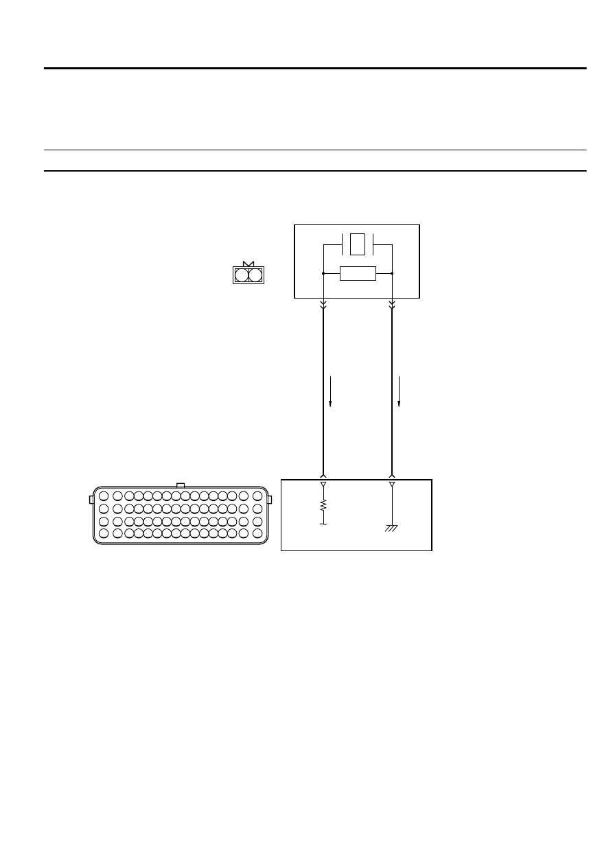
DTC DTC P0331: Knock Sensor Circuit Performance (Bank 2)

M11310100370USA0000010000

ZK602867

1

2

3 4 5 6 7 8 9 10 11 12 13 14 15 16

17 18 19 20 21 22 23 24 25 26 27 28 29 30 31 32

33 34 35 36 37 38 39 40 41 42 43 44 45 46 47 48

49 50 51 52 53 54 55 56 57 58 59 60 61 62 63 64

2

1

KNOCK SENSOR 2 CIRCUIT

KNOCK SENSOR 2

B-10

28

WHITE

BL

A

C

K

29

1

2

ENGINE
CONT RO L
MODULE

AA00

B-20 

MU802601

MULTIPORT INJECTION SYSTEM (MFI) <DIAGNOSIS>

13Ab-423

DIAGNOSTIC TROUBLE CODE PROCEDURES

ZK603636 AA00

Knock sensor 2

B-20 (B)

Connector: B-20

ZK603591

ECM

B-10 (GR)

Connector: B-10

AA00


CIRCUIT OPERATION

The knock sensor (terminal No. 1) sends a signal
voltage to the ECM (terminal No. 28).

The ground terminal (terminal No. 2) is grounded
with ECM (terminal No. 29)

TECHNICAL DESCRIPTION

The  knock  sensor  converts  the  vibration  of  the
cylinder block into a voltage and outputs it. If there
is  a  malfunction  of  the  knock  sensor,  the  voltage
output will not change.

The  ECM  checks  whether  the  voltage  output
changes.

DTC SET CONDITIONS

Check Conditions

2 seconds or more have passed since the engine
starting sequence was completed.

Engine speed is higher than 3,000 r/min.

Volumetric efficiency is 40 percent or higher.

Judgement Criterion

Knock sensor 2 output voltage (knock sensor peak
voltage in each 1/3 turn of the crankshaft) has not
changed more than 0.06 volt in the last consecutive
200 periods.

TROUBLESHOOTING HINTS (The most likely
causes for this code to be set are:)

Knock sensor 2 failed.

Harness damage.

Connector damage.

ECM failed.


DIAGNOSIS

Required Special Tools:

MB991958: Scan Tool (M.U.T.-III Sub Assembly)

MB991824: V.C.I.

MB991827: USB Cable

MB991910: Main Harness A

13Ab-424

MULTIPORT INJECTION SYSTEM (MFI) <DIAGNOSIS>

DIAGNOSTIC TROUBLE CODE PROCEDURES

STEP 1. Check harness connector B-20 at the knock sensor
2 and harness connector B-10 at ECM for damage.

Q:Is the harness connector in good condition?

YES:

 Go to Step 2.

NO:

 Repair or replace it. Refer to GROUP 00E, Harness

Connector Inspection P.00E-2. Then go to Step 4.

STEP 2. Check for harness damage between knock sensor
2 connector B-20 and ECM connector B-10.

ZK603877

16

15 14 13 12 11 10 9 8 7 6 5 4

3

2

1

32

31 30 29 28 27 26 25 24 23 22 21 20 19 18

17

48

47 46 45 44 43 42 41 40 39 38 37 36 35 34

33

64

63 62 61 60 59 58 57 56 55 54 53 52 51 50

49

1

2

AA00

B-06 harness connector: 
component side

B-10 harness connector: 
component side

(1)

Disconnect  the  connector  B-20  and  B-10  measure  at  the
harness side.

(2)

Measure  the  resistance  between  connector  B-20  and
connector B-10.

  a

.

Knock sensor 1 connector B-20 (terminal No. 1) and ECM
connector B-10 (terminal No. 28).

b
.

Knock sensor 1 connector B-20 (terminal No. 2) and ECM
connector B-10 (terminal No. 29).

Should be less than 2 ohms.

Q:Is the measured resistance less than 2 ohms?

YES:

 Then go to Step 3.

NO:

 Repair it. Then go to Step 4.

STEP 3. Replace the knock sensor 2.

ZC501967

AC404789

ZC5019680000

MB991824

MB991827

MB991910

Data link

connector

(1)

Replace the knock sensor 2.

To prevent damage to scan tool MB991958, always turn
the ignition switch to the "LOCK" (OFF) position before
connecting or disconnecting scan tool MB991958.

(2)

Connect scan tool MB991958 to the data link connector.

(3)

Turn the ignition switch to the "ON" position.

(4)

Erase the DTC.

(5)

Test drive under the following conditions:

Engine speed: 3,000 - 5,000 r/min

Engine load: 40 % or more

Drive a minimum of 3 seconds after the above conditions
have been met.

(6)

After completing the test drive, read the DTC.

(7)

Turn the ignition switch to the "LOCK" (OFF) position.

Q:Is DTC P0331 set?

YES:

 Replace the ECM. When the ECM is replaced, register

the ID code. Refer to GROUP 42B, ID Code Registration
Judgment Table <Vehicles with KOS> P.42B-12or GROUP
42C, ID Code Registration Judgment Table <Vehicles with
WCM> P.42C-8.

NO:

 The inspection is complete.

MULTIPORT INJECTION SYSTEM (MFI) <DIAGNOSIS>

13Ab-425

DIAGNOSTIC TROUBLE CODE PROCEDURES

STEP 4. Using scan tool MB991958, read the diagnostic
trouble code (DTC).

(1)

Turn the ignition switch to the "ON" position.

(2)

Test drive under the following conditions:

Engine speed: 3,000 - 5,000 r/min

Engine load: 40 % or more

Drive a minimum of 3 seconds after the above conditions
have been met.

(3)

After completing the test drive, read the DTC.

(4)

Turn the ignition switch to the "LOCK" (OFF) position.

Q:Is DTC P0331 set?

YES:

 Retry the troubleshooting.

NO:

 The inspection is complete.

DTC P0332: Knock Sensor Circuit Low (Bank 2)

M11310100371USA0000010000

ZK602867

1

2

3 4 5 6 7 8 9 10 11 12 13 14 15 16

17 18 19 20 21 22 23 24 25 26 27 28 29 30 31 32

33 34 35 36 37 38 39 40 41 42 43 44 45 46 47 48

49 50 51 52 53 54 55 56 57 58 59 60 61 62 63 64

2

1

KNOCK SENSOR 2 CIRCUIT

KNOCK SENSOR 2

B-10

28

WHITE

BL

A

C

K

29

1

2

ENGINE
CONT RO L
MODULE

AA00

B-20 

MU802601

13Ab-426

MULTIPORT INJECTION SYSTEM (MFI) <DIAGNOSIS>

DIAGNOSTIC TROUBLE CODE PROCEDURES


Content   ..  305  306  307  308   ..