Mitsubishi Outlander XL. Manual - part 231
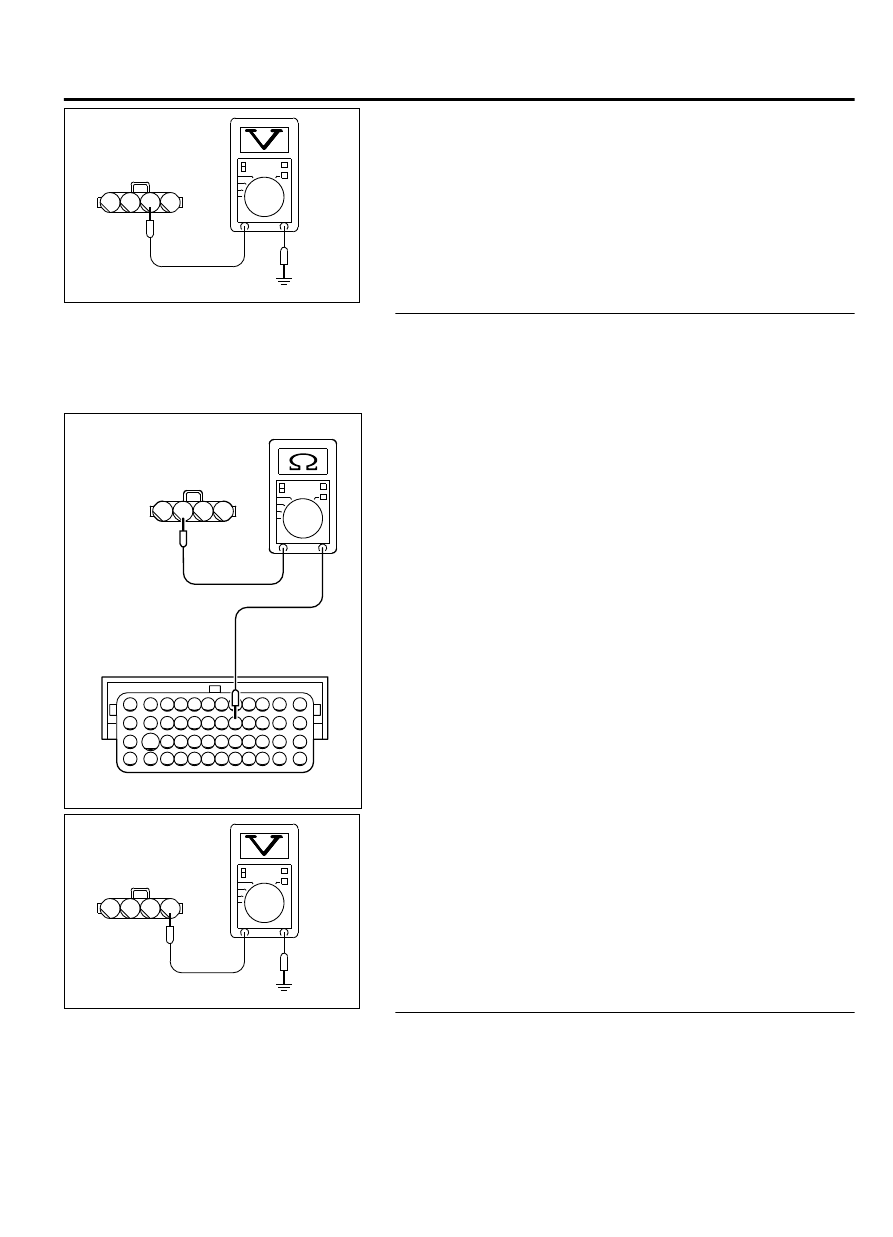
A-07 harness
connector:
component side
ZK603170AA00
2
1
3
4
(3)
Measure the voltage between terminal No. 2 and ground.
⦆
Voltage should be battery positive voltage.
(4)
Turn the ignition switch to the "LOCK" (OFF) position.
Q:Is battery positive voltage (approximately 12 volts)
present?
YES:
Go to Step 4.
NO:
Repair harness wire between the MFI relay connector
A-33X (terminal No. 2) and the mass airflow sensor A-07
(terminal No. 2) because of open circuit or short circuit
to ground. Then go to step 6.
STEP 4. Check for open circuit or short circuit to ground
between the mass airflow sensor connector A-07 and ECM
connector B-11.
(1)
Disconnect the mass airflow sensor A-07 and the ECM
connector B-10.
ZK604075
82 81 80 79 78 77 76 75 74 73 72 71
94 93 92 91 90 89 88 87 86 85 84 83
99 98 97 96 95
100
101
102
103
104
105
106
112
113
114
109 108
107
110
111
115
116
117
118
2
1
3
4
A-07 harness connector:
component side
B-11 harness connector:
component side
AA00
(2)
Measure the resistance between the mass airflow sensor
connector A-07 (terminal No. 3) and ECM connector B-11
(terminal No. 87).
⦆
Should be less than 2 ohms.
A-07 harness
connector:
component side
ZK603171AA00
2
1
3
4
(3)
Check for the continuity between the mass airflow sensor
A-07 (terminal No. 3) and ground.
⦆
Not continuity.
Q:Is the harness wire in good condition?
YES:
Go to Step 5.
NO:
Repair it. Then go to Step 6.
STEP 5. Replace the mass airflow sensor.
(1)
Replace the mass airflow sensor.
(2)
Carry out a test drive with the drive cycle pattern. Refer to
Diagnostic Function - OBD-II Drive Cycle - Pattern 24 P.
13Ab-8.
MULTIPORT INJECTION SYSTEM (MFI) <DIAGNOSIS>
13Ab-119
DIAGNOSTIC TROUBLE CODE PROCEDURES