Mitsubishi Outlander XL. Manual - part 229


  Index      Mitsubishi     Mitsubishi Outlander XL - service repair manual 2007 year


Search            


Content   ..  227  228  229  230   ..


Mitsubishi Outlander XL. Manual - part 229


DTC SET CONDITIONS <Range/Performance problem - high input>
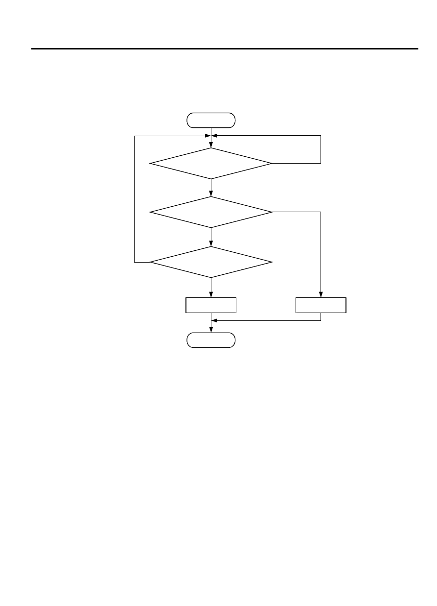
Logic Flow Chart

Start

End

No

No

Yes

Yes

Yes

No

Malfunction

Good

Continuous

failure for 2secs

Output voltage

>= 3.5V

Monitoring

conditions

AA00

ZK603674

Check Conditions

Throttle position sensor output voltage is 1.0 volt or
lower.

Mass airflow sensor output voltage is 4.9 volts or
lower.

Judgement Criterion

Mass airflow sensor output voltage has continued
to be 3.5 volts or higher for 2 seconds.

OBD-II DRIVE CYCLE PATTERN

Refer to Diagnostic Function - OBD-II Drive Cycle -
Pattern 7 P.13Ab-8.

TROUBLESHOOTING HINTS (The most likely
causes for this code to be set are: )

Mass airflow sensor failed.

Connector damage

Harness damage

ECM failed.


MULTIPORT INJECTION SYSTEM (MFI) <DIAGNOSIS>

13Ab-111

DIAGNOSTIC TROUBLE CODE PROCEDURES

DIAGNOSIS

Required Special Tools:

MB991958: Scan tool (M.U.T.-III Sub Assembly)

MB991824: V.C.I.

MB991827: USB Cable

MB991910: Main Harness A

STEP 1. Using scan tool MB991958, check data list item 10:
Mass Airflow Sensor.

ZC501967

AC404789

ZC5019680000

MB991824

MB991827

MB991910

Data link

connector

To prevent damage to scan tool MB991958, always turn the
ignition  switch  to  the  "LOCK"  (OFF)  position  before
connecting or disconnecting scan tool MB991958.

(1)

Connect scan tool MB991958 to the data link connector.

(2)

Start the engine and run at idle.

(3)

Set scan tool MB991958 to the data reading mode for item
10, Mass Airflow Sensor.

(4)

Warm up the engine to normal operating temperature: 80°C
to 95°C (176°F to 203°F).

The standard value during idling should be between 1,350
and 1,670 millivolts.

When the engine is revved, the mass airflow rate should
increase according to the increase in engine speed.

(5)

Turn the ignition switch to the "LOCK" (OFF) position.

Q:Is the sensor operating properly?

YES:

 It can be assumed that this malfunction is

intermittent. Refer to GROUP 00, How to Use
Troubleshooting/Inspection Service Points - How to Cope
with Intermittent Malfunctions P.00-15.

NO:

 Go to Step 2.

STEP 2. Check harness connector A-07 at the mass airflow
sensor and harness connector B-11 at the ECM for damage.

Q:Is the harness connector in good condition?

YES:

 Go to Step 3.

NO:

 Repair it. Refer to GROUP 00E, Harness Connector

Inspection P.00E-2. Then go to Step 6.

STEP 3. Check for harness damage between the mass
airflow sensor connector A-07 and the ECM connector B-11.

(1)

Disconnect the mass airflow sensor connector A-07 and the
ECM connector B-11.

13Ab-112

MULTIPORT INJECTION SYSTEM (MFI) <DIAGNOSIS>

DIAGNOSTIC TROUBLE CODE PROCEDURES

ZK603168

82 81 80 79 78 77 76 75 74 73 72 71

94 93 92 91 90 89 88 87 86 85 84 83

99 98 97 96 95

100

101

102

103

104

105

106

112

113

114

109 108

107

110

111

115

116

117

118

2

1

3

4

A-07 harness connector:
component side 

B-11 harness connector:
component side 

AA00

(2)

Measure  the  resistance  between  the  mass  airflow  sensor
connector A-07 and the ECM connector B-11.

a
.

Connector  A-07  (terminal  No.  3)  and  Connector  B-11
(terminal No. 87).

b
.

Connector  A-07  (terminal  No.  4)  and  Connector  B-11
(terminal No. 88).

Should be less than 2 ohms.

Q:Is the measured resistance less than 2 ohms?

YES:

 Go to Step 4.

NO:

 Repair it. Then go to Step 6.

STEP 4. Check for harness the MFI relay connector A-33X
(terminal No. 2) and the mass airflow sensor connector A-07
(terminal No. 2).

(1)

Disconnect  the  MFI  relay  connector  A-33X  and  the  mass
airflow sensor connector A-07.

ZK603169

2

1

3

4

3

1

2

4

A-07 harness connector:
component side 

A-33X harness 
connector:
component side 

AA00

(2)

Measure  the  resistance  between  the  MFI  relay  connector
A-33X  (terminal  No.  2)  and  the  mass  airflow  sensor  A-07
(terminal No. 2).

Should be less than 2 ohms.

Q:Is the measured resistance less than 2 ohms?

YES:

 Go to Step 5.

NO:

 Repair it. Then go to Step 6.

STEP 5. Replace the mass airflow sensor.

(1)

Replace the mass airflow sensor.

(2)

Carry out a test drive with the drive cycle pattern. Refer to
Diagnostic  Function  -  OBD-II  Drive  Cycle  -  Pattern  7  P.
13Ab-8.

(3)

Check the diagnostic trouble code (DTC).

Q:Is DTC P0101 set?

YES:

 Replace the ECM. When the ECM is replaced, register

the ID code. Refer to GROUP 42B, ID Code Registration

MULTIPORT INJECTION SYSTEM (MFI) <DIAGNOSIS>

13Ab-113

DIAGNOSTIC TROUBLE CODE PROCEDURES

Judgment Table <Vehicles with KOS> P.42B-12or GROUP
42C, ID Code Registration Judgment Table <Vehicles with
WCM> P.42C-8. Then go to Step 6.

NO:

 The inspection is complete.

STEP 6. Test the OBD-II drive cycle.

(1)

Carry out a test drive with the drive cycle pattern. Refer to
Diagnostic  Function  -  OBD-II  Drive  Cycle  -  Pattern  7  P.
13Ab-8.

(2)

Check the diagnostic trouble code (DTC).

Q:Is DTC P0101 set?

YES:

 Retry the troubleshooting.

NO:

 The inspection is complete.

13Ab-114

MULTIPORT INJECTION SYSTEM (MFI) <DIAGNOSIS>

DIAGNOSTIC TROUBLE CODE PROCEDURES


Content   ..  227  228  229  230   ..