Mitsubishi Outlander XL. Manual - part 230


  Index      Mitsubishi     Mitsubishi Outlander XL - service repair manual 2007 year


Search            


Content   ..  228  229  230  231   ..


Mitsubishi Outlander XL. Manual - part 230


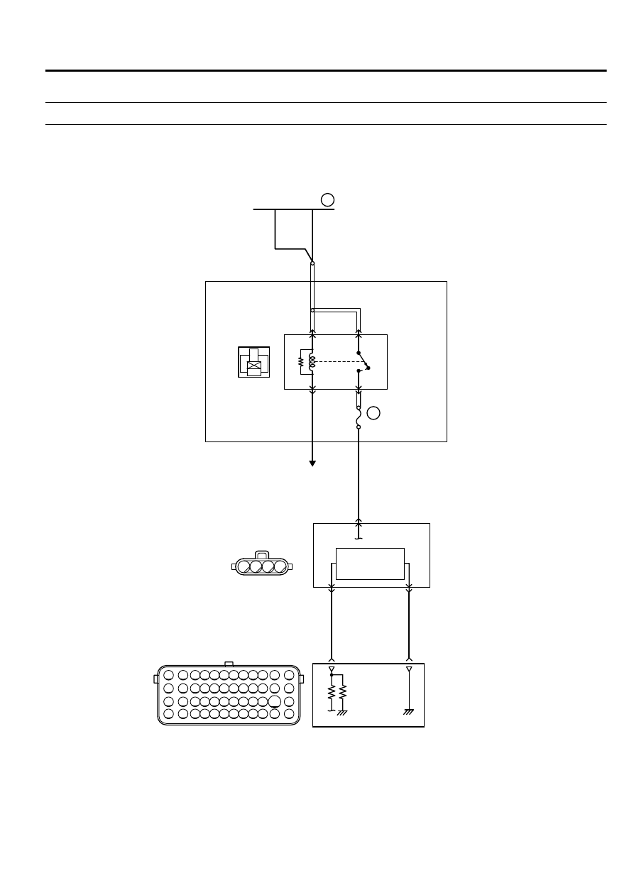
DTC P0102: Mass Airflow Circuit Low Input

M11310100171USA0000010000

ZK602833

71 72 73 74 75 76 77 78 79 80 81 82

83 84 85 86 87 88 89 90 91 92 93 94

95 96 97 98 99

100 101 102 103 104

112 113 114

109

108

107

110 111

115 116

106

105

118

117

1

3

2

4

3 4

2

1

AA00

MASS AIRFLOW SENSOR CIRCUIT

87

88

ENGINE
CONTROL
MODULE

MASS AIRFLOW SENSOR

3

2

HEAT
SENSITIZING
RESISTANCE

BLUE

A-07

(MU805110)

BLA

CK-WHITE

4

20A

WHITE

WHITE

WHITE

A-33X

MFI
RELAY

RELAY BOX
(ENGINE COMPARTMENT)

4

3

1

2

22

TO ECM

B-11

36

FUSIBLE LINK

OFF

ON

MULTIPORT INJECTION SYSTEM (MFI) <DIAGNOSIS>

13Ab-115

DIAGNOSTIC TROUBLE CODE PROCEDURES

ZK603589

MFI relay

A-33X

Connector: A-33X

AA00

ZK603596

Mass airflow

sensor

AA00

A-07 (GR)

Connector: A-07

ZK603592

ECM

B-11 (GR)

Connector: B-11

AA00


CIRCUIT OPERATION

The mass airflow sensor power is supplied from the
MFI  relay  (terminal  No.  4),  and  the  ground  is
provided on the ECM (terminal No. 88).

A voltage that is according to the mass airflow rate
is sent to the ECM (terminal No. 87) from the mass
airflow sensor output terminal (terminal No. 3).

TECHNICAL DESCRIPTION

While the engine is running, the mass airflow sensor
outputs  voltage  which  corresponds  to  the  mass
airflow rate.

The ECM checks whether the voltage output by the
mass airflow sensor while the engine is running is
within a specified range.

DESCRIPTIONS OF MONITOR METHODS

Mass  airflow  sensor  output  voltage  is  out  of
specified range.

MONITOR EXECUTION

Continuous

MONITOR EXECUTION CONDITIONS (Other
monitor and Sensor)

Other Monitor (There is no temporary DTC stored in
memory for the item monitored below)

Not applicable

Sensor (The sensor below is determined to be
normal)

Not applicable

13Ab-116

MULTIPORT INJECTION SYSTEM (MFI) <DIAGNOSIS>

DIAGNOSTIC TROUBLE CODE PROCEDURES

DTC SET CONDITIONS

Logic Flow Chart

End

Malfunction

Yes

Yes

Yes

No

No

No

Continuous

failure for 2secs

Output voltage

< 0.2V

Output voltage

> 4.9V

Monitoring

conditions

Good

Start

ZK603676 AA00

Yes

No

Check Conditions

3 seconds or more have passed since the ignition
switch was turned to "ON" position.

Judgement Criterion

Mass airflow sensor output voltage has continued
to be 0.2 volt or lower for 2 seconds.

OBD-II DRIVE CYCLE PATTERN

Refer to Diagnostic Function - OBD-II Drive Cycle -
Pattern 24 P.13Ab-8.

TROUBLESHOOTING HINTS (The most likely
causes for this code to be set are: )

Mass airflow sensor failed.

Connector damage

Harness damage

ECM failed.


MULTIPORT INJECTION SYSTEM (MFI) <DIAGNOSIS>

13Ab-117

DIAGNOSTIC TROUBLE CODE PROCEDURES

DIAGNOSIS

Required Special Tools:

MB991958: Scan tool (M.U.T.-III Sub Assembly)

MB991824: V.C.I.

MB991827: USB Cable

MB991910: Main Harness A

STEP 1. Using scan tool MB991958, check data list item 10:
Mass Airflow Sensor.

ZC501967

AC404789

ZC5019680000

MB991824

MB991827

MB991910

Data link

connector

To prevent damage to scan tool MB991958, always turn the
ignition  switch  to  the  "LOCK"  (OFF)  position  before
connecting or disconnecting scan tool MB991958.

(1)

Connect scan tool MB991958 to the data link connector.

(2)

Start the engine and run at idle.

(3)

Set scan tool MB991958 to the data reading mode for item
10, Mass Airflow Sensor.

(4)

Warm up the engine to normal operating temperature: 80°C
to 95°C (176°F to 203°F).

The standard value during idling should be between 1,350
and 1,670 millivolts.

When the engine is revved, the mass airflow rate should
increase according to the increase in engine speed.

(5)

Turn the ignition switch to the "LOCK" (OFF) position.

Q:Is the sensor operating properly?

YES:

 It can be assumed that this malfunction is

intermittent. Refer to GROUP 00, How to Use
Troubleshooting/Inspection Service Points - How to Cope
with Intermittent Malfunctions P.00-15.

NO:

 Go to Step 2.

STEP 2. Check harness connector A-07 at the mass airflow
sensor and harness connector B-11 at the ECM for damage.

Q:Is the harness connector in good condition?

YES:

 Go to Step 3.

NO:

 Repair it. Refer to GROUP 00E, Harness Connector

Inspection P.00E-2. Then go to Step 6.

STEP 3. Measure the power supply voltage at the mass
airflow sensor harness side connector A-07.

(1)

Disconnect the connector A-07 and measure at the harness
side.

(2)

Turn the ignition switch to the "ON" position.

13Ab-118

MULTIPORT INJECTION SYSTEM (MFI) <DIAGNOSIS>

DIAGNOSTIC TROUBLE CODE PROCEDURES


Content   ..  228  229  230  231   ..