Mitsubishi Outlander XL. Manual - part 232
DTC SET CONDITIONS
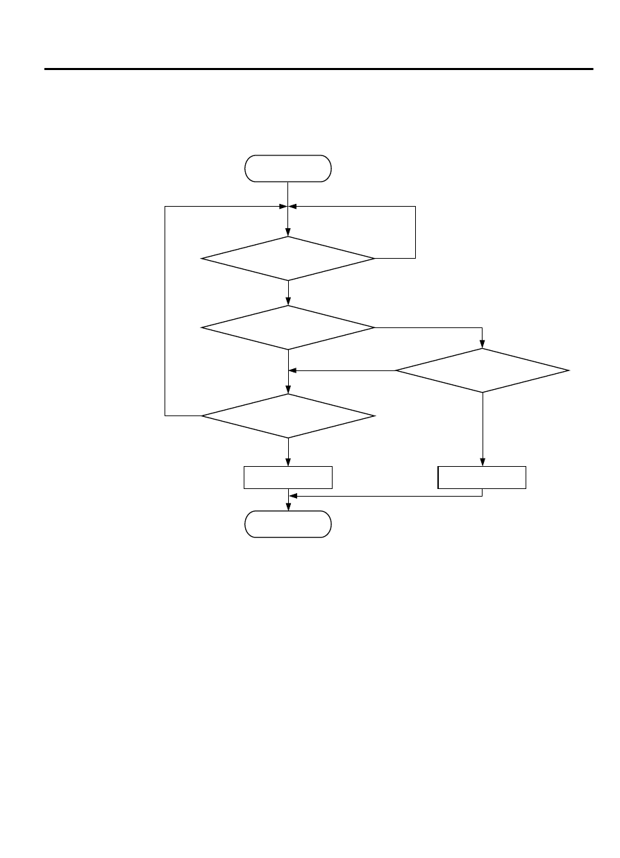
Logic Flow Chart
End
Malfunction
Yes
Yes
Yes
No
No
No
Continuous
failure for 2secs
Output voltage
< 0.2V
Output voltage
> 4.9V
Monitoring
conditions
Good
Start
ZK603676 AA00
Yes
No
Check Conditions
⦆
3 seconds or more have passed since the ignition
switch was turned to "ON" position.
Judgement Criterion
⦆
Mass airflow sensor output voltage has continued
to be higher than 4.9 volts for 2 seconds.
OBD-II DRIVE CYCLE PATTERN
Refer to Diagnostic Function - OBD-II Drive Cycle -
Pattern 24 P.13Ab-8.
TROUBLESHOOTING HINTS (The most likely
causes for this code to be set are: )
⦆
Mass airflow sensor failed.
⦆
Connector damage
⦆
Harness damage
⦆
ECM failed.
MULTIPORT INJECTION SYSTEM (MFI) <DIAGNOSIS>
13Ab-123
DIAGNOSTIC TROUBLE CODE PROCEDURES