Mitsubishi Outlander XL. Manual - part 191
6.
Install the engine oil filler cap.
7.
Let the engine run for a few minutes.
8.
Stop the engine, and then check the oil level using the oil
dipstick after a few minutes.
ENGINE OIL FILTER REPLACEMENT
M11201000011USA0000010000
1.
Start the engine and allow it to warm up until the temperature
of the coolant reaches 80 - 90°C (176 - 194°F)
Use care as oil could be hot.
2.
Remove the engine oil filler cap.
3.
Remove the drain plug to drain oil.
ZC601081
MB991828,
MB991396
or equivalent
0000
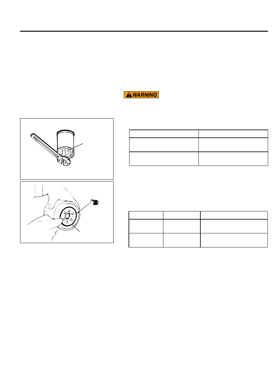
4.
Use the respective tool in the following table to remove the
engine oil filter.
Number
Special tool
MD332687 or MD365876
Oil filter wrench (MB991828)
or equivalent
MD360935
Oil filter wrench (MB991396)
or equivalent
5.
Clean the filter bracket side mounting surface and ensure the
old O-ring has been removed.
ZC601082
O-ring
0001
6.
Apply a small amount of engine oil to the O-ring of the new oil
filter.
7.
Screw on the oil filter by hand until it touches the surface of
the flange and then tighten it with an oil filter wrench.
Number
Special tool
Tightening torque
MD332687 or
MD365876
MB991828 or
equivalent
Approximately 3/4 turn [16 ±
4 N·m (12 ± 3 ft-lb)]
MD360935
MB991396 or
equivalent
Approximately one turn [14 ±
2 N·m (124 ± 18 in-lb)]
8.
Install the drain plug and refill engine oil (Refer to P.12-4).
9.
Rev the engine a few times, and check to be sure that no
engine oil leaks at the oil filter.
ENGINE OIL PRESSURE CHECK
M11201000023USA0000010000
1.
Check engine oil quantity.
ENGINE LUBRICATION
12-5
ON-VEHICLE SERVICE