Mitsubishi Outlander XL. Manual - part 189


  Index      Mitsubishi     Mitsubishi Outlander XL - service repair manual 2007 year


Search            


Content   ..  187  188  189  190   ..


Mitsubishi Outlander XL. Manual - part 189


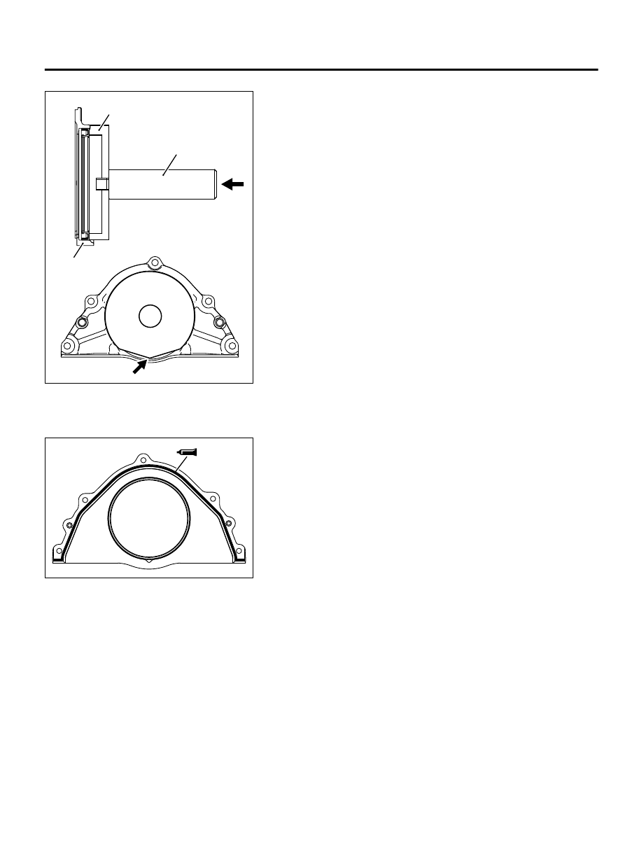
>>F<< CRANKSHAFT REAR OIL SEAL INSTALLATION

ZK600653

MB992183

Oil seal 
case

MB992075

0000

Edge

Using special tools MB992075 and MB992183, press-fit a new
crankshaft rear oil seal into the oil seal case.

NOTE: 

Put the edge position in place as shown in the

illustration.


>>G<< OIL SEAL CASE INSTALLATION

ZK602461AA00

1.

Apply  a  2.5  ±  0.5  mm  (0.10  ±  0.01  inch)  diameter  bead  of
sealant (Three bond 1227D [MZ100792] or equivalent) to the
oil seal case.

2.

Apply a small amount of engine oil to the entire circumference
of the oil seal lip section, and place the oil seal case on the
cylinder block.

NOTE: 

Install the oil seal case within 15 minutes after

applying liquid gasket.

NOTE: 

Then wait at least one hour. Never start the engine

or let engine oil or coolant touch the adhesion surface
during that time.


>>H<< DRIVE PLATE BOLT INSTALLATION

1.

Cleanly remove sealant, oil and dust on the drive plate bolt,
the drive plate and the threaded portions of the crankshaft.

ENGINE OVERHAUL

11B-75

CRANKSHAFT AND CYLINDER BLOCK

ZK6006720000

2.

Apply oil to the drive plate and the seating surface of the drive
plate bolt.

3.

Apply oil to the threaded hole of the crankshaft

4.

Apply sealant (Three bond 1324 or equivalent) to the thread
portions of the drive plate bolt.

ZK602109AA00

MD998781

5.

Using special tool MD998781, hold the drive plate.

6.

Tighten the drive plate bolt to the specified torque.

Tightening torque: 76 ± 4 N·m (57 ± 2 ft-lb)

CYLINDER BLOCK INSPECTION

M11103000916USA0000010000

ZK602462AA00

1.

Using a straightedge and thickness gauge, check the block
top surface for warpage. Make sure that the surface is free
from gasket chips and other objects.

Standard value: 0.05 mm (0.002 inch)
Limit: 0.1 mm (0.004 inch)

2.

If the distortion is excessive, replace the cylinder block.

ZK602463

64 mm

(2.52 in)

12 mm

(0.47 in)

115 mm

(4.53 in)

AA00

3.

Check cylinder walls for scratches and seizure. If defects are
evident, correct (bored to oversize) or replace.

4.

Using  a  cylinder  gauge,  measure  the  cylinder  bore,  and
cylindricity. If worn badly, correct cylinder to an oversize and
replace  piston  and  piston  rings.  Measurement  points  are
shown in illustration.

Standard value

Cylinder I.D.: 87.6 mm (3.45 inch)
Cylindricity: 0.015 mm (0.0006 inch)

CRANKSHAFT OIL CLEARANCE (PLASTIGAGE

METHOD)

M11103000915USA0000010000

The crankshaft oil clearance can be measured easily by using a
plastigage, as follows:

11B-76

ENGINE OVERHAUL

CRANKSHAFT AND CYLINDER BLOCK

1.

Remove oil and grease and any other foreign matters from
crankshaft journal and bearing inner surface.

2.

Install the crankshaft.

ZK6021110000

Plastigage

3.

Cut the plastigage to the same length as the width of bearing
and place it on journal in parallel with its axis.

ZK6021100000

4.

Gently place the crankshaft bearing cap over it and tighten the
bolts to the specified torque.

5.

Remove the bolts and gently remove the crankshaft bearing
cap.

6.

Measure  the  width  of  the  smashed  plastigage  at  its  widest
section by using a scale printed on the plastigage bag.

Standard value:

Number 1 and 4 journal
0.018 - 0.038 mm (0.0008 - 0.0014 inch)
Number 2 and 3 journal
0.024 - 0.044 mm (0.0010 - 0.0017 inch)

Limit: 0.1 mm (0.004 inch)

ENGINE OVERHAUL

11B-77

CRANKSHAFT AND CYLINDER BLOCK

MEMO

11B-78

ENGINE OVERHAUL


Content   ..  187  188  189  190   ..