Mitsubishi Outlander XL. Manual - part 188


  Index      Mitsubishi     Mitsubishi Outlander XL - service repair manual 2007 year


Search            


Content   ..  186  187  188  189   ..


Mitsubishi Outlander XL. Manual - part 188


Required Special Tools:

MB992075: Handle

MB992183: Crankshaft Rear Oil Seal Installer

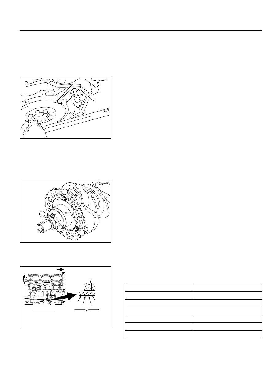
MD998781: Flywheel Stopper

REMOVAL SERVICE POINT

<<A>> DRIVE PLATE BOLT REMOVAL

ZK602109AA00

MD998781

1.

Using special tool MD998781, hold the drive plate.

2.

Remove the drive plate bolt.

INSTALLATION SERVICE POINTS

>>A<< CRANKSHAFT SENSING RING INSTALLATION

1.

Apply  the  engine  oil  to  the  thread  portions  and  the  sealed
portions on the installation bolts.

ZK6006540000

1

2

3

2.

In  accordance  with  the  tightening  order  shown  in  the
illustration, tighten the crankshaft sensing ring to the specified
torque.

Tightening torque: 12 ± 2 N·m (106 ± 17 in-lb)


>>B<< CRANKSHAFT BEARING UPPER INSTALLATION

ZK600656

No.4

Cylinder 
bore size

No.3 No.2

No.1

0000

Right side

Timing belt side

Crankshaft journal (Upper)

identification mark

1.

If the upper crankshaft bearing is replaced, select based on
the identification mark of cylinder block (illustrated) and the
table shown below.

Crankshaft journal (Upper) Crankshaft bearing
Identification mark

Identification mark

Number 1 and 4 journal
1

1

2

2

3

3

Number 2 and 3 journal

ENGINE OVERHAUL

11B-71

CRANKSHAFT AND CYLINDER BLOCK

Crankshaft journal (Upper) Crankshaft bearing
Identification mark

Identification mark

0

0

1

1

2

2

ZK6006570000

Identification
mark

2.

The upper crankshaft bearing has the identification mark on
the location shown in the illustration.

3.

Install the upper selected crankshaft bearing.


>>C<< CRANKSHAFT THRUST BEARING INSTALLATION

ZK500353AA00

Groove

1.

Install  the  thrust  bearing  in  the  No.3  bearing  bore  in  the
cylinder block and in the bearing cap. For easier installation,
apply  engine  oil  to  the  bearings;  this  will  help  hold  them  in
position.

2.

The thrust bearings must be installed with their groove toward
the crankshaft web.


>>D<< CRANKSHAFT BEARING LOWER INSTALLATION

ZK600655

Crankshaft
No.5 jornal

No.1

Model name

2D code

No.2

No.3

No.4

Spare

0000

Crankshaft pin

identification mark

Crankshaft journal (Lower)

identification mark

1.

If the lower crankshaft bearing is replaced, select based on the
identification  mark  of  crankshaft  (illustrated)  and  the  table
shown below.

Crankshaft journal (Lower) Crankshaft bearing
Identification mark

Identification mark

0

0

1

1

2

2

3

3

4

4

11B-72

ENGINE OVERHAUL

CRANKSHAFT AND CYLINDER BLOCK

ZK6006580000

Identification
mark

2.

The lower crankshaft bearing has the identification mark on
the location shown in the illustration.

3.

Install the lower selected crankshaft bearing.


>>E<< BEARING CAP / BEARING CAP BOLT
INSTALLATION

ZK604073 0000

Shank length

1.

Before  installing  the  bearing  cap  bolt,  check  the  bolt  screw
head  is  not  damaged.  If  the  screw  head  extremely  gets
damaged, replace it with a new bolt. The standard length of
the new bolt measured from under the head is as follows:

Standard value: 91.2 - 92.2 mm (3.59 - 3.63 inches)


ZK601900

5

8

7

4

2

3

1

6

5

8

7

2

3

4

1

6

0000

Front mark

Crankshaft

Cylinder block

2.

Attach the bearing cap on the cylinder block as shown in the
illustration.

3.

Tighten  the  bearing  cap  bolts  to  specified  torque  in  the
sequence shown in the illustration.

ENGINE OVERHAUL

11B-73

CRANKSHAFT AND CYLINDER BLOCK

Tightening torque: 24 ± 2 N·m (18 ± 1 ft-lb)

ZK601901AA00

Paint mark

Paint mark

90˚

4.

Make a paint mark on the head of each bolt.

If the bolt is overtightened, loosen the bolt completely and
then  retighten  it  by  repeating  the  tightening  procedure
from step 2.

If the bolt is turned less than 90 degrees, proper fastening
performance may not be achieved. Be sure to turn the bolt
exactly 90 degrees.

5.

Make a paint mark on the bearing cap 90 degrees from the
paint mark made on the bolt, in the direction of tightening the
bolt.

6.

Turn  each  bolt  90  degrees  in  the  tightening  sequence
specified in step 2, and make sure that the paint marks on the
bolt and cap are aligned.

7.

Check that the crankshaft rotates smoothly.

ZK602460AA00

8.

Check the end play. If it exceeds the limit value, replace the
thrust bearing.

Standard value: 0.05 - 0.25 mm (0.002 - 0.009 inch)
Limit: 0.3 mm (0.01 inch)


11B-74

ENGINE OVERHAUL

CRANKSHAFT AND CYLINDER BLOCK


Content   ..  186  187  188  189   ..