Mitsubishi Outlander XL. Manual - part 186


  Index      Mitsubishi     Mitsubishi Outlander XL - service repair manual 2007 year


Search            


Content   ..  184  185  186  187   ..


Mitsubishi Outlander XL. Manual - part 186


REMOVAL SERVICE POINTS

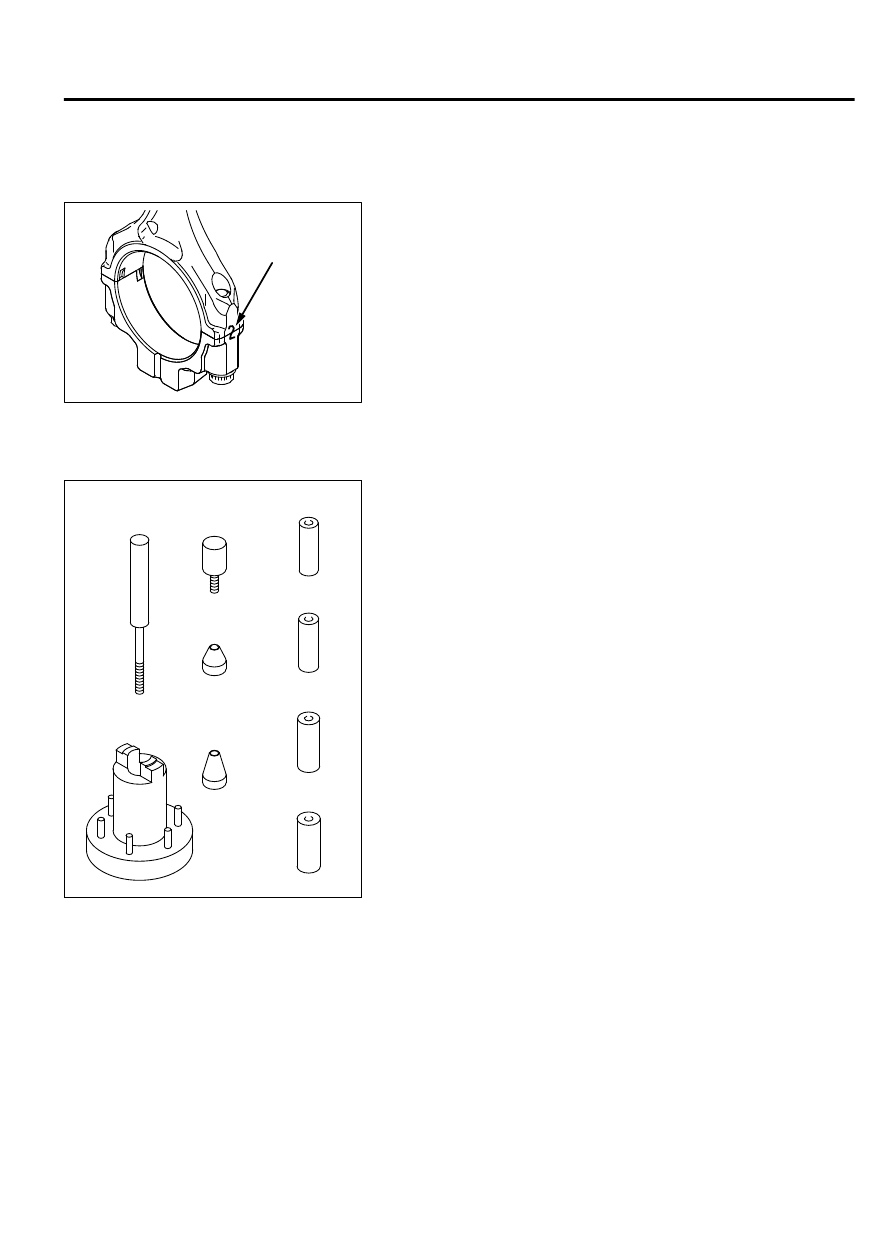
<<A>> CONNECTING ROD CAP REMOVAL

ZK602114

Cylinder number

0000

1.

Mark the cylinder number on the side of the connecting rod
big end for correct reassembly.

2.

Keep  the  removed  connecting  rods,  caps,  and  bearings  in
order according to the cylinder number.


<<B>> PISTON PIN REMOVAL

ZK602503AA00

Guide A:
21.9 mm (0.86 in)

Guide A:
20.9 mm (0.82 in)

Guide A:
18.9 mm (0.74 in)

Guide A: 
17.9 mm (0.70 in)

Guide B

Guide C

Guide D

(MB991659)

Base

Push rod

MD998780

1.

The special tool MD998780 consists of the elements shown in
the illustration.

2.

When removing the piston pin, the special tool MB991659 is
also used.

ENGINE OVERHAUL

11B-63

PISTON AND CONNECTING ROD

ZK602504 AA00

Base

Guide D
(MB991659)

Front mark

Push rod

P

View P

Front mark
(Oil jet hole)

3.

Insert Push rod, into the piston from the front mark side, then
attach Guide D, to the push rod.

4.

Place the piston and connecting rod assembly on Base, with
the front mark facing up.

5.

Use a press to remove the piston pin.

NOTE: 

Keep the disassembled pistons, piston pins and

connecting rods per cylinder.

INSTALLATION SERVICE POINTS

>>A<< PISTON PIN INSTALLATION

ZK600659

Crankshaft
bore size

0000

Timing belt side

No.6

No.5

No.1

No.2

No.3

Cylinder 
bore size

Right side

No.4

1.

When replacing the piston, note the cylinder bore size mark on
the cylinder block as illustrated, and select a piston according
to the flowing table.

Cylinder bore size mark

Piston size mark

A

A

B

B

NOTE: 

The piston size mark shows on the top of the piston.

2.

Insert the push rod into the piston pin and install the guide A.

3.

Align the front mark of the piston with that of the connecting
rod. Align the piston with the connecting rod.

4.

Apply engine oil to the outer circumference of the piston pin.

5.

Insert the piston pin guide A installed at step 2 into the pin hole
from the front mark of the piston.

ZK602506

Guide A

Guide B

Push rod

L

AA00

Front mark

6.

Screw the guide B into A until the clearance "L" reaches 3.75
mm (0.147 inch) between A and B.

11B-64

ENGINE OVERHAUL

PISTON AND CONNECTING ROD

ZK602505AA00

View P

Front mark
(Oil jet hole)

Front mark

Push rod

P

Base

Guide A

Guide B

7.

Place the piston and connecting rod assembly onto Base, with
the front marks facing up.

8.

Install the piston pin using a press. If the required press force
is less than the standard value, replace the piston and piston
pin assembly or the connecting rod, or both.

Standard value: 5,000 - 15,000 N (1,124 - 3,372 pound)

ZK602450AA00

9.

Check that the piston moves smoothly.


>>B<< OIL RING INSTALLATION

ZK500351

Spacer

AA00

Lower side rail

Upper side rail

1.

Fit the oil ring spacer into the piston ring groove.

NOTE: 

The side rails and spacer may be installed in

either direction.

Do  not  use  any  piston  ring  expander  when  installing  the
side rail. If will break the side rail.

ENGINE OVERHAUL

11B-65

PISTON AND CONNECTING ROD

ZK602451AA00

2.

Install the upper side rail.
To install the side rail, first fit one end of the rail into the piston
groove, then press the remaining portion into the position by
finger. See illustration.

3.

Install the lower side rail in the same procedure as described
in step 2.

4.

Make sure that the side rails move smoothly in both directions.


>>C<< PISTON RING NO.2 / PISTON RING NO.1
INSTALLATION

ZK500319

No. 2

No. 1

AA00

Identification mark

To prevent wrong installation, check the identification mark of
each piston ring. The identification mark is stamped near the ring
gap:

Identification mark

Number 1 ring: 1T
Number 2 ring: 2T


>>D<< CONNECTING ROD BEARING INSTALLATION

ZK600667

No.1

Crankshaft pin

identification mark

Model
name

2D code

No.2

No.3

No.4

No.5

No.6

Spare

0000

Crankshaft journal (Lower)

identification mark

Crankshaft
No.5 jornal

1.

If the connecting rod bearing is replaced, select based on the
identification  mark  of  crankshaft  (illustrated)  and  the  table
shown below.

Crankshaft pin

Bearing

Identification mark

Identification color

1

Black

2

Purple

3

Green

ZK6006680000

Identification color

2.

Every connecting rod bearing is identified by the identification
color at the illustrated location.

3.

Install the selected bearing in the big end and in the cap of the
connecting rod.


11B-66

ENGINE OVERHAUL

PISTON AND CONNECTING ROD


Content   ..  184  185  186  187   ..