Mitsubishi Outlander XL. Manual - part 185
2.
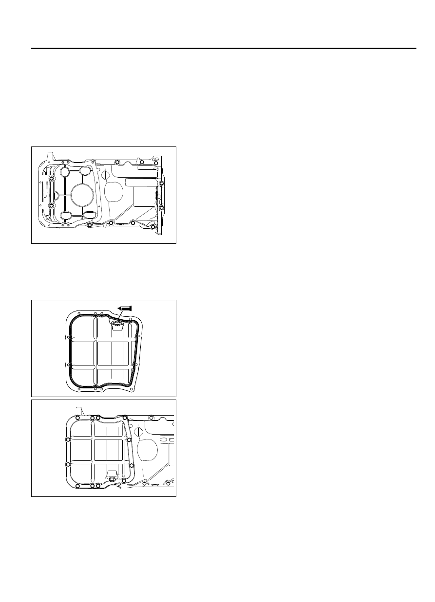
Apply a 2.5 ± 0.5 mm (0.10 ± 0.01 inch) diameter bead of
sealant (Three bond 1227D [MZ100792] or equivalent) to the
oil pan. Be sure to install the oil pan quickly while the sealant
is wet.
NOTE:
Install the oil pan within 15 minutes after
applying liquid gasket.
NOTE:
Then wait at least one hour. Never start the engine
or let engine oil or coolant touch the adhesion surface
during that time.
ZK6006690000
1
3
5
9
6
2
4
8
10
11
7
3.
Tighten the upper oil pan bolts in the sequence shown.
Tightening torque: 10 ± 2 N·m (89 ± 12 in-lb)
4.
After installation, keep the sealed area away from the oil and
coolant for approximately one hour.
>>F<< OIL PAN LOWER INSTALLATION
1.
Clean the gasket surfaces of the cylinder block and oil pan
lower.
ZK6006640000
2.
Apply a 2.5 ± 0.5 mm (0.10 ± 0.01 inch) diameter bead of
sealant (Three bond 1227D [MZ100792] or equivalent) to the
oil pan. Be sure to install the oil pan quickly while the sealant
is wet.
NOTE:
Install the oil pan within 15 minutes after
applying liquid gasket.
NOTE:
Then wait at least one hour. Never start the engine
or let engine oil or coolant touch the adhesion surface
during that time.
ZK6006650000
3
2
5
11 9
8 12
10
1
4
7
6
3.
Tighten the upper oil pan bolts in the sequence shown.
Tightening torque: 10 ± 2 N·m (89 ± 12 in-lb)
4.
After installation, keep the sealed area away from the oil and
coolant for approximately one hour.
ENGINE OVERHAUL
11B-59
OIL PAN AND OIL PUMP