Mitsubishi Outlander XL. Manual - part 183


  Index      Mitsubishi     Mitsubishi Outlander XL - service repair manual 2007 year


Search            


Content   ..  181  182  183  184   ..


Mitsubishi Outlander XL. Manual - part 183


ZK500354AA00

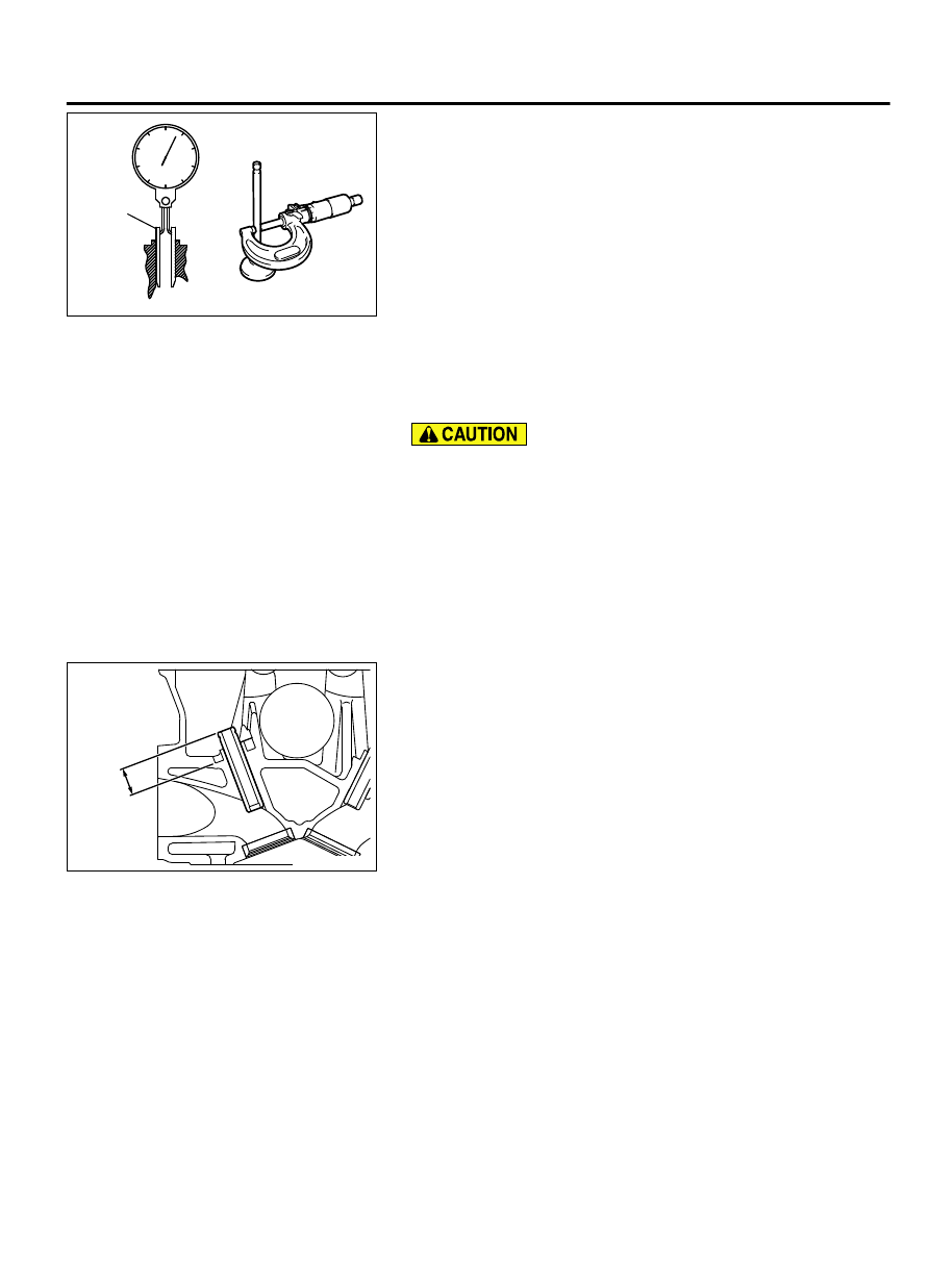
Guide inside diameter

Stem diameter

Valve 
guide

Measure the clearance between the valve guide and valve stem.
If it exceeds the limit, replace the valve guide or valve, or both.

Standard value:

Intake 0.020 - 0.047 mm (0.0008 - 0.0018 inch)
Exhaust 0.035 - 0.062 mm (0.0014 - 0.0024 inch)

Limit:

Intake 0.10 mm (0.003 inch)
Exhaust 0.15 mm (0.005 inch)

VALVE GUIDE REPLACEMENT PROCEDURE

1.

Using  a  press,  remove  the  valve  guide  toward  the  cylinder
block.

Do not install a valve guide of the same size again.

2.

Rebore the valve guide hole of the cylinder head so that it fits
the press-fitted oversize valve guide.

Valve guide hole diameters

0.05 oversize: 11.050 - 11.068 mm (0.4351 - 0.4357
inch)
0.25 oversize: 11.250 - 11.268 mm (0.4430 - 0.4436
inch)
0.50 oversize: 11.500 - 11.518 mm (0.4528 - 0.4535
inch)

ZK602123 0000

Protrusion

3.

Press-fit  the  valve  guide  until  it  projects  by  the  specified
amount.

Protrusion: 16.7 - 17.3 mm (0.66 - 0.68 inch)

NOTE: 

When press-fitting the valve guide, work from the

cylinder head top surface.

NOTE: 

Pay attention to the difference in length of the

valve guides. [Intake side: 45.5 mm (1.79 inches);
exhaust side: 52.5 mm (2.07 inches)]

NOTE: 

After installing the valve guides, insert new

valves in them to check for smooth operation.

VALVE SEAT INSPECTION

M11103000909USA0000010000

ENGINE OVERHAUL

11B-51

CYLINDER HEAD AND VALVES

ZK6021240000

Valve seat

Contact width

Assemble  the  valve,  then  measure  the  contact  width.  If  the
measurement exceeds the specified limit, replace the valve seat.

Standard value: 0.9 - 1.3 mm (0.36 - 0.51 inch)

VALVE SEAT REPLACEMENT PROCEDURE

ZK500349AA00

Cut

0.5 – 1.0 mm
(0.02 – 0.04 in)

0.5 – 1.0 mm
(0.02 – 0.04 in)

1.

Cut the valve seat from the inside to thin the wall thickness.
Then, remove the valve seat.

ZK500350AA00

Oversize hole
diameter

Valve seat
height

2.

Rebore the valve seat hole in the cylinder head to a selected
oversize valve seat diameter.

Intake seat ring hole diameters

0.3 oversize:
36.30 - 36.33 mm (1.4292 - 1.4301 inches)

Exhaust seat ring hole diameters

0.3 oversize:
32.30 - 32.33 mm (1.2717 - 1.2726 inches)

3.

Before fitting the valve seat, either heat the cylinder head up
to approximately 250°C (482°F) or cool the valve seat in liquid
nitrogen, to prevent the cylinder head bore from galling.

4.

Using  a  valve  seat  cutter,  correct  the  valve  seat  to  the
specified width and angle.
See  "VALVE  SEAT  RECONDITIONING  PROCEDURE"  on
the previous page.

11B-52

ENGINE OVERHAUL

CYLINDER HEAD AND VALVES

VALVE SEAT RECONDITIONING PROCEDURE

ZK602125

0.9 

 1.3 mm

(0.36 

 0.51 in)

44°

65°

30°

30°

44°

65°

AA00

1.

Before correcting the valve seat, check for clearance between
the valve guide and valve and, if necessary, replace the valve
guide.

2.

Using  the  seat  grinder,  correct  to  obtain  the  specified  seat
width and angle.

3.

After correcting the valve seat, lap the valve and valve seat
using  lapping  compound.  Then,  check  the  valve  stem
projection.

OIL PAN AND OIL PUMP

REMOVAL AND INSTALLATION

M11103000081USA0000010000

ENGINE OVERHAUL

11B-53

OIL PAN AND OIL PUMP

ZK600033

10 ± 2 N·m
89 ± 17 in-lb

10 ± 2 N·m
89 ± 17 in-lb

10 ± 2 N·m
89 ± 17 in-lb

10 ± 2 N·m
89 ± 17 in-lb

23 ± 6 N·m
17 ± 4 ft-lb

6

2

1

8

10

16

11

9

7

23 ± 6 N·m
17 ± 4 ft-lb

20 ± 5 N·m
15 ± 3 ft-lb

39 ± 5 N·m
29 ± 3 ft-lb

17

4

3

18

20

AA01

12

13

24 ± 2 N·m
18 ± 1 ft-lb


+60°

Apply engine oil to
all moving parts
before installation.

23 ± 6 N·m
17 ± 4 ft-lb

19

10 ± 2 N·m
89 ± 17 in-lb

5

14

15

23 ± 6 N·m
17 ± 4 ft-lb

Removal steps

1.

DRAIN PLUG

>>J<<

2.

DRAIN PLUG GASKET

>>I<<

3.

OIL FILTER

>>H<<

4.

OIL FILTER COVER

5.

HEAT PROTECTOR

>>G<<

6.

ENGINE OIL PRESSURE SWITCH

<<A>>

>>F<<

7.

OIL PAN, LOWER

8.

OIL PAN COVER

<<B>>

>>E<<

9.

OIL PAN, UPPER

10. OIL SCREEN

>>D<<

11. OIL SCREEN GASKET

Removal steps

>>C<<

12. BEARING CAP BOLT

>>C<<

13. BEAM

>>C<<

14. RIGHT PLATE

>>C<<

15. LEFT PLATE

>>B<<

16. CRANKSHAFT FRONT OIL SEAL

>>A<<

17. OIL PUMP CASE
18. O-RING
19. O-RING
20 O-RING

11B-54

ENGINE OVERHAUL

OIL PAN AND OIL PUMP


Content   ..  181  182  183  184   ..