Mitsubishi Outlander XL. Manual - part 175


  Index      Mitsubishi     Mitsubishi Outlander XL - service repair manual 2007 year


Search            


Content   ..  173  174  175  176   ..


Mitsubishi Outlander XL. Manual - part 175


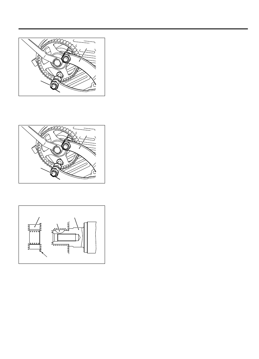
<<D>> CAMSHAFT SPROCKET BOLT REMOVAL

ZK602101AA00

MB990767

MD998719

Use  special  tools  MB990767  and  MD998719  to  prevent  the
camshaft sprocket from turning, and then loosen the camshaft
sprocket bolt.

INSTALLATION SERVICE POINTS

>>A<< CAMSHAFT SPROCKET BOLT INSTALLATION

ZK602101AA00

MB990767

MD998719

Use  special  tools  MB990767  and  MD998719  to  prevent  the
camshaft sprocket from turning, and then tighten the camshaft
sprocket bolt.

Tightening torque: 90 ± 10 N·m (65 ± 7 ft-lb)


>>B<< CRANKSHAFT SPROCKET INSTALLATION

ZK600044

Crankshaft

Crankshaft
sprocket

Clean

0000

Key

1.

Clean the hole in the crankshaft sprocket.

2.

Clean  and  degrease  the  mating  surfaces  of  the  crankshaft
sprocket.

NOTE: 

Degreasing is necessary to prevent decrease in

friction on the mating surfaces.

3.

Install the crankshaft sprocket to the crankshaft.


ENGINE OVERHAUL

11B-19

TIMING BELT

>>C<< IDLER PULLEY INSTALLATION

ZK602452

Idler pulley

Hexagon socket
head bolt

0000

Because of the shallow hexagon hole of the hexagon socket
head bolt, firmly insert the tool and carefully work not to
damage the hexagon hole.
Install the idler pulley using a hexagon wrench with 8 mm width
across flats.


>>D<< AUTO-TENSIONER INSTALLATION

Always bleed the auto-tensioner of air before installing the
auto-tensioner.  (Refer  to  auto  tensioner  inspection  P.
11B-23
.)


>>E<< TIMING BELT INSTALLATION

Remove  and  install  the  timing  belt,  aligning  the  timing
marks  of  the  crankshaft  sprocket  and  the  camshaft
sprocket  with  the  No.1  at  the  Top  Dead  Center  of  the
compression stroke.

ZK600057

Camshaft sprocket

Timing marks

Right bank

Left bank

0000

ZK6000560000

Timing mark

Timing mark

Camshaft sprocket

1.

Check  the  timing  marks  of  the  crankshaft  sprocket  and  the
camshaft sprocket are aligned with the No.1 at the Top Dead
Center  of  the  compression  stroke.  If  they  are  not,  align  the
timing  marks  again,  paying  attention  to  the  interference
between the valve and the piston.

2.

Install  the  timing  belt  on  each  sprocket  in  the  following
sequence.

(1)

Install the timing belt on the crankshaft sprocket and then
on  the  water  pump  pulley,  while  tightening  it  to  prevent
slackness.

(2)

Line  up  the  timing  marks  of  the  left  bank  camshaft
sprockets.

(3)

Install the timing belt on the idler pulley, while taking up the
slack.

(4)

Install the timing belt on the right bank camshaft sprocket.

(5)

Install the timing belt on the tensioner pulley.

3.

Check to see that the timing marks of all the sprockets are in
a alignment.

11B-20

ENGINE OVERHAUL

TIMING BELT

ZK6000590000

MD998716

4.

Using special tool MD998716, rotate the crankshaft a quarter
of a turn counterclockwise. Then rotate it back clockwise to
verify that all the timing marks are in alignment.

5.

Pull out the pin of the auto-tensioner.


ZK600054 0000

Timing mark

Camshaft sprocket

Camshaft sprocket

Water pump pulley

Crankshaft sprocket

Idler pulley

Auto tensioner

Tensioner pulley

Timing mark

Timing mark

Timing mark

Right bank

Left bank

6.

Rotate the crankshaft two turns clockwise and leave it alone
for approximately five minutes.

ENGINE OVERHAUL

11B-21

TIMING BELT

ZK6000550000

7.

Check that the projection of the rod of the auto-tensioner is
within the standard value.

Standard value: 9.1 - 13.4 mm (0.36 - 0.52 inch)

TIMING BELT INSPECTION

M11103000946USA0000010000

Replace the belt if any of the following conditions exist:

ZK6019140000

1.

Hardening of rubber backing.
Back side should be glossy without resilience and leave no
indent when pressed with fingernail.

ZK6019150000

Cracks

Peeling of canvas

Cracks in tooth roots

Cracks

Cracks in sides

2.

Cracks on rubber back.

3.

Cracks or peeling of canvas.

4.

Cracks at bottom of ribs.

5.

Cracks on belt sides.

ZK6019160000

Rounded edge

Abnormal wear 
(Fluffy strand)

6.

Abnormal wear of belt sides. Normal wear is indicated if the
sides are sharp as if cut by a knife. Abnormal wear is indicated
if the sides are ragged.

11B-22

ENGINE OVERHAUL

TIMING BELT


Content   ..  173  174  175  176   ..