Mitsubishi Outlander XL. Manual - part 173
ZK600041
23 ± 6 N·m
17 ± 4 ft-lb
1
3
4
5
6
7
8
9
10
11
12
13
16
15
47 ± 11 N·m
35 ± 7 ft-lb
200 N·m
148 ft-lb
0 N·m
0 ft-lb
23 ± 6 N·m
17 ± 4 ft-lb
23 ± 6 N·m
17 ± 4 ft-lb
47 ± 11 N·m
35 ± 7 ft-lb
2
23 ± 6 N·m
17 ± 4 ft-lb
14
AA01
→
→
110 N·m
81 ft-lb
→
+60°
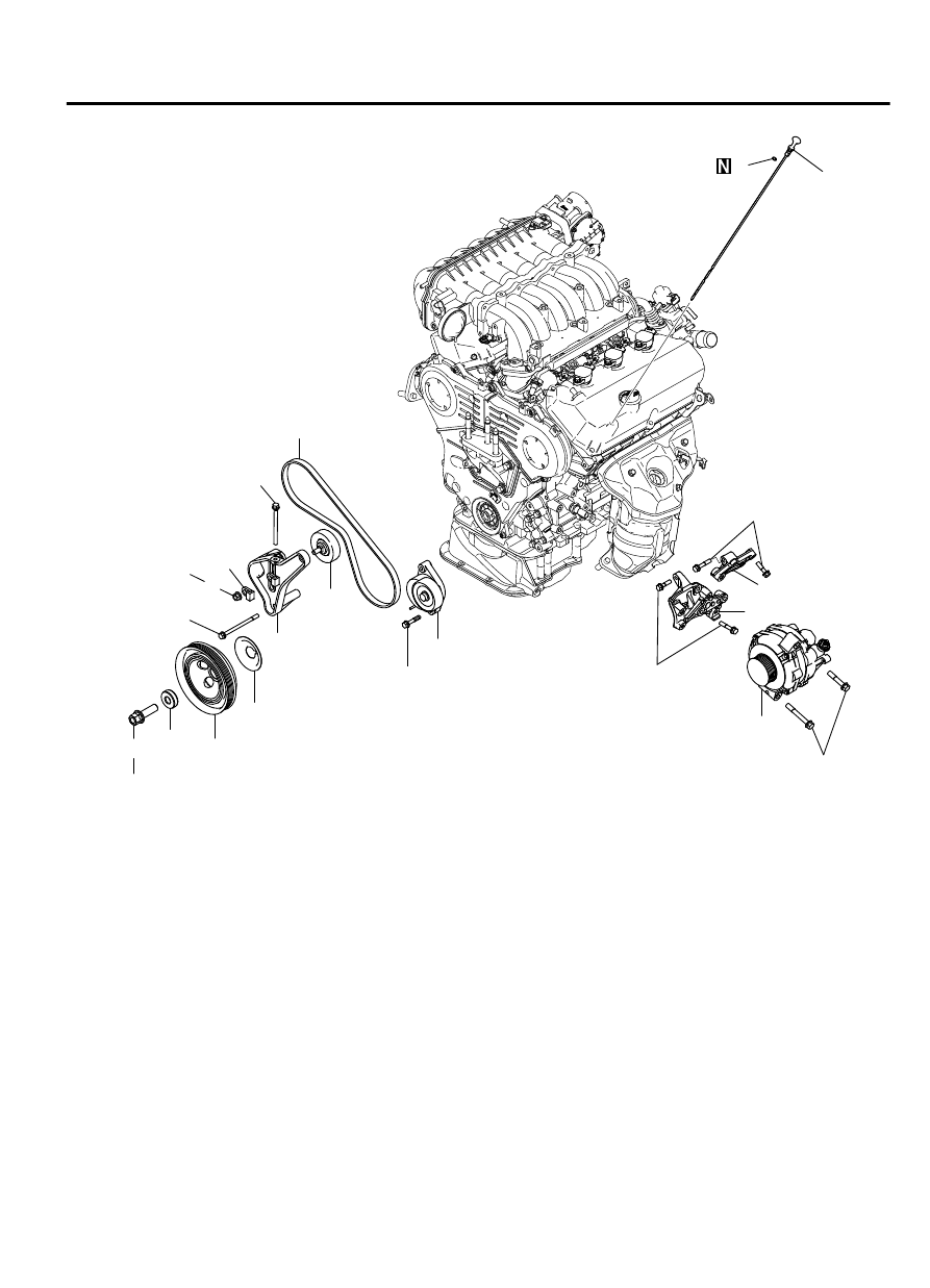
Removal steps
1.
OIL DIPSTICK
2.
O-RING
3.
DRIVE BELT
<<A>>
>>B<<
4.
CRANKSHAFT BOLT
5.
CRANKSHAFT PULLEY WASHER
6.
CRANKSHAFT PULLEY
7.
FRONT FLANGE
8.
FLANGE NUT
9.
ADJUSTING NUT
Removal steps
10. FLANGE BOLT
11. TENSIONER PULLEY
12. POWER
STEERING
TENSIONER
PULLEY BRACKET
13. DRIVE BELT AUTO TENSIONER
>>A<<
14. GENERATOR
15. GENERATOR BRACKET UPPER
16. GENERATOR BRACKET LOWER
Required Special Tool:
⦆
MD998781: Flywheel Stopper
ENGINE OVERHAUL
11B-11
GENERATOR