Mitsubishi Outlander XL. Manual - part 166


  Index      Mitsubishi     Mitsubishi Outlander XL - service repair manual 2007 year


Search            


Content   ..  164  165  166  167   ..


Mitsubishi Outlander XL. Manual - part 166


INSTALLATION SERVICE POINTS

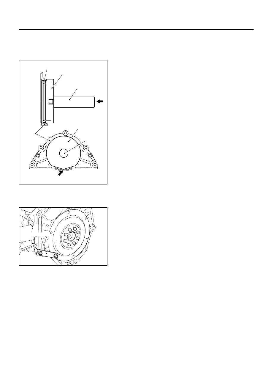
>>A<< CRANKSHAFT REAR OIL SEAL INSTALLATION

ZC603634

Edge

Oil seal

MB992183

MB992075

MB992183

Oil seal 
case

AA00

MB992075

Use  special  tool  MB992075  and  MB992183,  press-fit  a  new
crankshaft rear oil seal into the oil seal case.


>>B<< DRIVE PLATE BOLTS INSTALLATION

ZC6017630000

MD998781

1.

Use special tool MD998781 to secure the drive plate in the
same manner as removal.

2.

Tighten the drive plate bolts to the specified torque.

Tightening torque: 74 ± 1 N·m (54 ± 1 ft-lb)

CYLINDER HEAD GASKET

REMOVAL AND INSTALLATION

M11102000040USA0000010001

Pre-removal and Post-installation Operation

Intake Manifold Removal and Installation (Refer to GROUP 15, Intake Manifold P.15-8).

Exhaust Manifold Removal and Installation (Refer to GROUP 15, Exhaust Manifold P.15-11).

Timing Belt Removal and Installation (Refer to P.11A-49).

Thermostat Housing Removal and Installation (Refer to GROUP 14, Water Hose and Water Pipe P.14-23).

ENGINE MECHANICAL

11A-45

CYLINDER HEAD GASKET

Generator Removal and Installation (Refer to GROUP 16a, Generator Assembly P.16a-13).

ZC600599

(Engine oil)

(Engine oil)

90 ± 10 N·m
67 ± 7 ft-lb

90 ± 10 N·m
67 ± 7 ft-lb

41 ± 10 N·m
30 ± 8 ft-lb

30 ± 3 N·m
22 ± 2 ft-lb

30 ± 3 N·m
22 ± 2 ft-lb

11 ± 1 N·m
98 ± 8 in-lb

8.3 ± 1.0 N·m
74 ± 8 in-lb

9.5 ± 2.5 N·m
84 ± 22 in-lb

8.3 ± 1.0 N·m
74 ± 8 in-lb

<Cold engine>
45 ± 2 N·m
33 ± 1 ft-lb
      to
+150° – +154°

1

2

3

4

5

6

7

8

9

9

10

11

11

12

13

14

15

16

17

18

19

20

21

22

23

24

25

26

9.5 ± 2.5 N·m
84 ± 22 in-lb

N

N

N

N

10 ± 2 N·m
89 ± 17 in-lb

N

N

AA00

<Cold engine>
45 ± 2 N·m
33 ± 1 ft-lb
      to
+150° – +154°

Removal steps

1.

Blow-by hose connection

2.

PCV hose connection

3.

Engine oil dipstick

4.

Ignition coil connector

5.

Ignition coil

6.

Rocker cover

7.

Rocker cover gasket

8.

Oil pipe

9.

Gasket

10. Camshaft position sensor connector

<<A>>

>>B<<

11. Camshaft sprocket

Removal steps

12. Idler pulley
13. Timing belt rear cover

<<B>>

>>A<<

14. Left bank cylinder head assembly
15. Cylinder head gasket
16. Blow-by hose connection
17. Breather hose connection
18. Ignition coil connector
19. Ignition coil
20. Rocker cover
21. Rocker cover gasket
22. Engine oil control valve connector

11A-46

ENGINE MECHANICAL

CYLINDER HEAD GASKET

Removal steps

23. Engine oil pressure switch connector
24. Solenoid valve connector

<<B>>

>>A<<

25. Right bank cylinder head assembly

Removal steps

26. Cylinder head gasket


Required Special Tools:

MB990767: End Yoke Holder

MB991614: Angle Gauge

MD998719: Pin

REMOVAL SERVICE POINTS

<<A>> CAMSHAFT SPROCKET REMOVAL

ZC6006010000

MB990767

MD998719

Use  special  tools  MB990767  and  MD998719  to  remove  the
camshaft sprocket.


<<B>> CYLINDER HEAD ASSEMBLY REMOVAL

ZC6024940000

Engine front

<Right
bank>

<Left
bank>

1

2

3

4

5

6

7

8

1

2

3

4

5

6

7

8

Loosen the bolts in two or three steps in the order of the numbers
shown in the illustration, and remove them.

INSTALLATION SERVICE POINTS

>>A<< CYLINDER HEAD ASSEMBLY INSTALLATION

Be careful that no foreign material gets into the cylinder,
coolant  passages  or  oil  passages.  Engine  damage  may
result.

1.

Use a scraper to clean the gasket surface of the cylinder head
assembly.

ENGINE MECHANICAL

11A-47

CYLINDER HEAD GASKET

ZC601792AA00

ZC6024940001

Engine front

<Right
bank>

<Left
bank>

1

2

3

4

5

6

7

8

1

2

3

4

5

6

7

8

2.

Tighten the bolts to the specified torque in the order shown in
the illustration. (in two or three cycles)

Tightening torque: 45 ± 2 N·m (33 ± 1 ft-lb)

ZC602502

150° to 154°

MB991614

AA00

If the bolt is turned less than 150 to 154 degrees, proper
fastening performance may not be achieved. Be sure to
turn the bolt exactly 150 to 154 degrees.

If the bolts is overtightened, loosen the bolt completely
and  then  retighten  it  by  repeating  the  tightening
procedure from step 1.

3.

Using special tool MB991614, tighten the cylinder head bolt
another 150 to 154 degrees.


>>B<< CAMSHAFT SPROCKET INSTALLATION

ZC6006010000

MB990767

MD998719

1.

Use special tools MB990767 and MD998719 in the same way
as during removal to install the camshaft sprocket.

2.

Tighten the camshaft sprocket mounting bolt to the specified
torque.

Tightening torque: 90 ± 10 N·m (67 ± 7 ft-lb)

11A-48

ENGINE MECHANICAL

CYLINDER HEAD GASKET


Content   ..  164  165  166  167   ..