Mitsubishi Outlander XL. Manual - part 1210


  Index      Mitsubishi     Mitsubishi Outlander XL - service repair manual 2007 year


Search            


Content   ..  1208  1209  1210  1211   ..


Mitsubishi Outlander XL. Manual - part 1210


OPERATION

CONDENSER FAN AND RADIATOR FAN
CONTROL
The  ECM  judges  the  required  revolution  speed  of
radiator fan motor and condenser fan motor using the
input signals transmitted from A/C switch, output shaft
speed  sensor  and  engine  coolant  temperature
sensor.

COMPRESSOR CONTROL

When operating the A/C switch

The  air  thermo  sensor,  which  senses  the
temperature of the air flowing out of the evaporator,
deactivates  the  compressor  at  3°C  (37.4°F)  or
below.

The  A/C  pressure  sensor  turns  OFF  when  the
refrigerant  pressure  becomes  excessively  high  or
low,  thus  protecting  the  compressor  circuit  (See
Table below).

When the air thermo sensor is activated, and the
ignition switch, blower switch, and A/C switch are
ON, the A/C compressor clutch relay is energized.

When operating the mode selection dial

The A/C will work when the mode selection dial is
set to the "Defroster" or "Defroster/foot" position, or
the temperature control dial is set to the "MAXIMUM
A/C" position. In other dial positions, when the A/C
switch is turned on, the A/C will work.


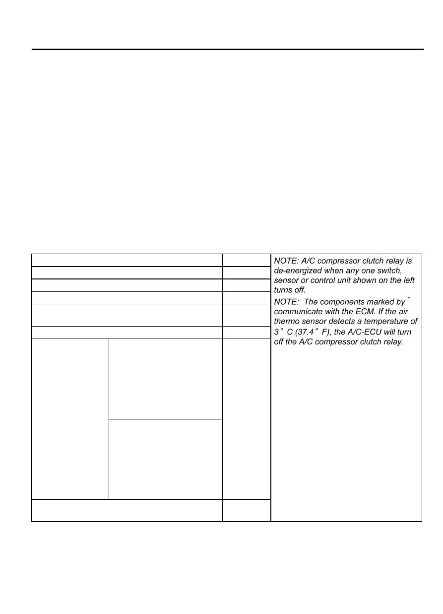
A/C Compressor Clutch Relay ON Conditions

Ignition switch (IG2)

ON

Blower speed selection dial

ON

A/C switch

ON

Mode selection dial

defroster

Temperature control dial

MAXIMUM
A/C

Air thermo sensor

*

Pressure  detected
by  A/C  pressure
sensor

2.94 MPa (427 psi) or less [If
the

 refrigerant

 pressure

exceeds  2.94  MPa  (427  psi),
A/C compressor clutch relay is
not  ON  condition  until  the
refrigerant pressure has been
measured  up  to  2.35  MPa
(341 psi) or less.]

ON

0.19  MPa  (27psi)  or  more  [If
the  refrigerant  pressure  falls
short of 0.19 MPa (27psi), A/C
compressor clutch relay is not
ON

 condition

 until

 the

refrigerant pressure has been
measured  up  to  0.22  MPa
(32psi) or more.]

A/C  compressor  clutch  relay  driving  transistor
(within ECM)

ON

AUTOMATIC AIR CONDITIONING

55B-3

GENERAL DESCRIPTION

AUTO A/C DIAGNOSIS

INTRODUCTION

M15504000062USA0000010000

After air is taken in through the damper, it is fed to the
evaporator by the blower fan and motor and cooled.
The  air  cooled  by  the  air  mix  damper  is  mixed
appropriately  with  the  warmed  air  to  achieve  a

comfortable temperature. If the A/C does not operate
or  the  cooled  air  is  not  discharged,  the  system
components or relay may be faulty.

AUTOMATIC A/C TROUBLESHOOTING STRATEGY

M15504000047USA0000010000

Use  these  steps  to  plan  your  diagnostic  strategy.  If
you  follow  them  carefully,  you  will  be  sure  that  you
have exhausted most of the possible ways to find a
heater, air conditioning and ventilation fault.

1.

Gather information from the customer.

2.

Verify that the condition described by the customer
exists.

3.

Find  the  malfunction  by  following  the  Symptom
Chart. (Refer to P.55B-10.)

4.

Verify malfunction is eliminated.

DIAGNOSTIC FUNCTION

M15504000976USA0000010000

HOW TO CONNECT THE SCAN TOOL (M.U.T.-III)

Required Special Tools:

MB991958: Scan Tool (M.U.T.-III Sub Assembly)

MB991824: Vehicles Communication Interface (V.C.I.)

MB991827: M.U.T.-III USB Cable

MB991910:  M.U.T.-III  Main  Harness  A  (Vehicles  with
CAN communication system)

ZC501967

AC404789

ZC5019680000

MB991824

MB991827

MB991910

Data link

connector

To prevent damage to scan tool MB991958, always turn the
ignition  switch  to  the  "LOCK"  (OFF)  position  before
connecting or disconnecting scan tool MB991958.

1.

Ensure that the ignition switch is at the "LOCK" (OFF) position.

2.

Start up the personal computer.

3.

Connect special tool MB991827 to special tool MB991824 and
the personal computer.

4.

Connect special tool MB991910 to special tool MB991824

5.

Connect special tool MB991910 to the data link connector.

6.

Turn the power switch of special tool MB991824 to the "ON"
position.

NOTE: 

When the special tool MB991824 is energized, the

special tool MB991824 indicator light will be illuminated
in a green color.

7.

Start the M.U.T.-III system on the personal computer.

NOTE: 

Disconnecting scan tool MB991958 is the reverse of

the connecting sequence, making sure that the ignition
switch is at the "LOCK" (OFF) position.

55B-4

AUTOMATIC AIR CONDITIONING

AUTO A/C DIAGNOSIS

HOW TO READ AND ERASE DIAGNOSTIC

TROUBLE CODES

Required Special Tools:

MB991958: Scan Tool (M.U.T.-III Sub Assembly)

MB991824: Vehicles Communication Interface (V.C.I.)

MB991827: M.U.T.-III USB Cable

MB991910:  M.U.T.-III  Main  Harness  A  (Vehicles  with
CAN communication system)

To prevent damage to scan tool MB991958, always turn the
ignition  switch  to  the  "LOCK"  (OFF)  position  before
connecting or disconnecting scan tool MB991958.

NOTE: 

If the battery voltage is low, diagnostic trouble

codes will not be set. Check the battery if scan tool
MB991958 does not display.

1.

Connect the scan tool MB991958 to the data link connector.

2.

Turn the ignition switch to the "ON" position.

3.

Select "System select" from the start-up screen.

4.

Select "From 2006 MY" of "Model Year." When the "Vehicle
Information" is displayed, check the contents.

5.

Select  "Air  Conditioner"  from  "System  List",  and  press  the
"OK" button.

NOTE: 

When the "Loading Option Setup" list is displayed,

check the applicable item.

6.

Select "Diagnostic Trouble Code."

7.

If a DTC is set, it is shown.

8.

Choose "Erase DTCs" to erase the DTC.

HOW TO READ DATA LIST

Required Special Tools:

MB991958: Scan Tool (M.U.T.-III Sub Assembly)

MB991824: Vehicles Communication Interface (V.C.I.)

MB991827: M.U.T.-III USB Cable

MB991910:  M.U.T.-III  Main  Harness  A  (Vehicles  with
CAN communication system)

To prevent damage to scan tool MB991958, always turn the
ignition  switch  to  the  "LOCK"  (OFF)  position  before
connecting or disconnecting scan tool MB991958.

1.

Connect the scan tool MB991958 to the data link connector.

2.

Turn the ignition switch to the "ON" position.

3.

Select "System select" from the start-up screen.

4.

Select "From 2006 MY" of "Model Year." When the "Vehicle
Information" is displayed, check the contents.

AUTOMATIC AIR CONDITIONING

55B-5

AUTO A/C DIAGNOSIS

5.

Select  "Air  Conditioner"  from  "System  List",  and  press  the
"OK" button.

NOTE: 

When the "Loading Option Setup" list is displayed,

check the applicable item.

6.

Select "Data List."

7.

Choose an appropriate item and select the "OK" button.

HOW TO PERFORM ACTUATOR TEST

Required Special Tools:

MB991958: Scan Tool (M.U.T.-III Sub Assembly)

MB991824: Vehicles Communication Interface (V.C.I.)

MB991827: M.U.T.-III USB Cable

MB991910:  M.U.T.-III  Main  Harness  A  (Vehicles  with
CAN communication system)

To prevent damage to scan tool MB991958, always turn the
ignition  switch  to  the  "LOCK"  (OFF)  position  before
connecting or disconnecting scan tool MB991958.

1.

Connect the scan tool MB991958 to the data link connector.

2.

Turn the ignition switch to the "ON" position.

3.

Select "System select" from the start-up screen.

4.

Select "From 2006 MY" of "Model Year." When the "Vehicle
Information" is displayed, check the contents.

5.

Select  "Air  Conditioner"  from  "System  List",  and  press  the
"OK" button.

NOTE: 

When the "Loading Option Setup" list is displayed,

check the applicable item.

6.

Select "Actuator Test."

7.

Choose an appropriate item and select the "OK" button.

HOW TO DIAGNOSE THE CAN BUS LINE

Required Special Tools:

MB991958: Scan Tool (M.U.T.-III Sub Assembly)

MB991824: Vehicles Communication Interface (V.C.I.)

MB991827: M.U.T.-III USB Cable

MB991910:  M.U.T.-III  Main  Harness  A  (Vehicles  with
CAN communication system)

To prevent damage to scan tool MB991958, always turn the
ignition  switch  to  the  "LOCK"  (OFF)  position  before
connecting or disconnecting scan tool MB991958.

1.

Connect scan tool MB991958 to the data link connector.

2.

Turn the ignition switch to the "ON" position.

3.

Select "CAN bus diagnosis" from the start-up screen.

4.

When  the  vehicle  information  is  displayed,  confirm  that  it
matches the vehicle whose CAN bus lines will be diagnosed.

If they match, go to step 8.

55B-6

AUTOMATIC AIR CONDITIONING

AUTO A/C DIAGNOSIS


Content   ..  1208  1209  1210  1211   ..