Content .. 1206 1207 1208 1209 ..
Mitsubishi Outlander XL. Manual - part 1208
ZC6020480000
2
1
4
4.9 ± 0.9 N·m
43 ± 8 in-lb
1, 2
3
3
N
3
N
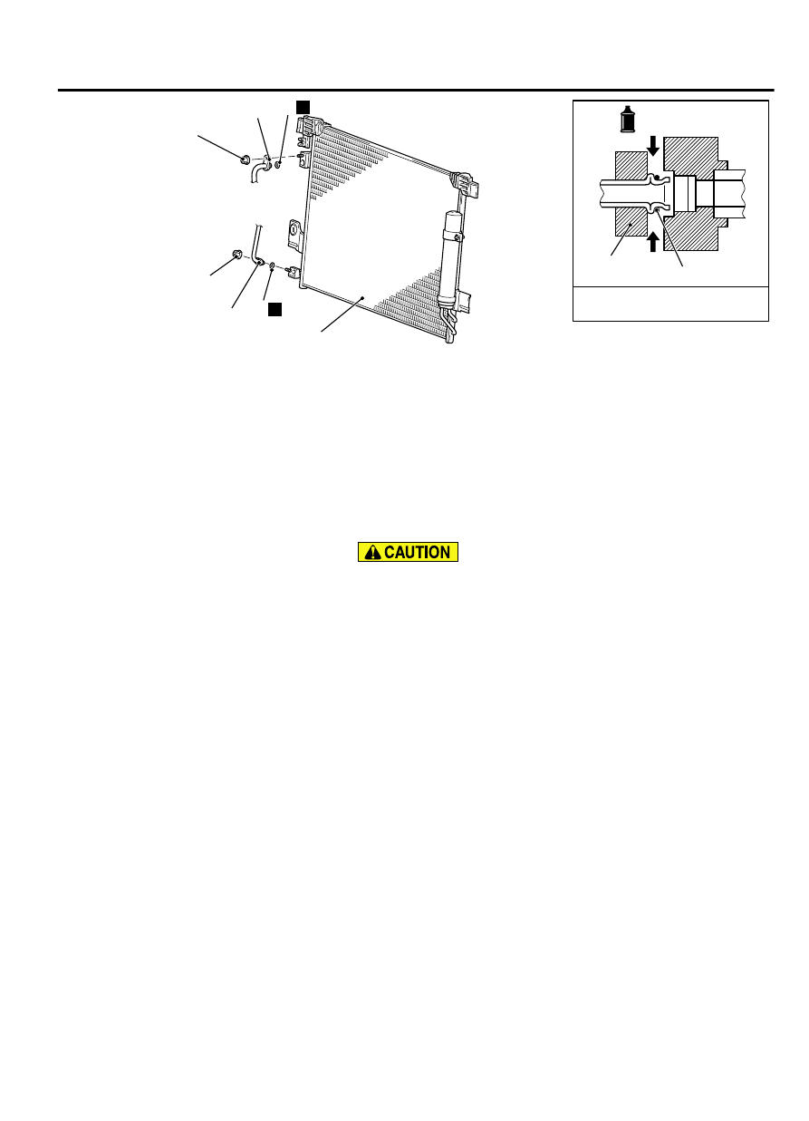
-Pipe coupling
A/C compressor oil:
SUN PAG 56
4.9 ± 0.9 N·m
43 ± 8 in-lb
Condenser removal steps
<<A>>
1.
Flexible discharge hose connection
<<A>>
2.
Liquid pipe A connection
3.
O-ring
Condenser removal steps
·
Front under cover
4.
Condenser assembly
REMOVAL SERVICE POINTS
<<A>> FLEXIBLE DISCHARGE HOSE AND LIQUID PIPE A
DISCONNECTION
As the compressor oil and receiver are highly moisture
absorbent, use a non-porous material to plug the hose and
nipples.
To prevent the entry of dust or other foreign bodies, plug the
dismantled hose and condenser assembly nipples.
INSTALLATION SERVICE POINT
>>A<< CONDENSER INSTALLATION
When replacing the condenser, refill it with a specified amount
of compressor oil and install it to the vehicle.
Compressor oil: SUN PAG 56
Quantity: 15 cm3(0.5 fl.oz)
REFRIGERANT LINE
REMOVAL AND INSTALLATION
M15502000064USA0000010000
Pre-removal and Post-installation Operation
⦆
Refrigerant Draining and Refilling (Refer to Charging and Discharging P.55A-125).
AIR CONDITIONING
55A-123
REFRIGERANT LINE