Mitsubishi Outlander XL. Manual - part 1211


  Index      Mitsubishi     Mitsubishi Outlander XL - service repair manual 2007 year


Search            


Content   ..  1209  1210  1211  1212   ..


Mitsubishi Outlander XL. Manual - part 1211


If not, go to step 5.

5.

Select "view vehicle information" button.

6.

When the vehicle information is displayed, confirm again that
it matches the vehicle which is being diagnosed.

If they match, go to step 8.

If not, go to step 5.

7.

Press the "OK" button.

8.

When the options are displayed, choose the options (mark the
check) and then select "OK".

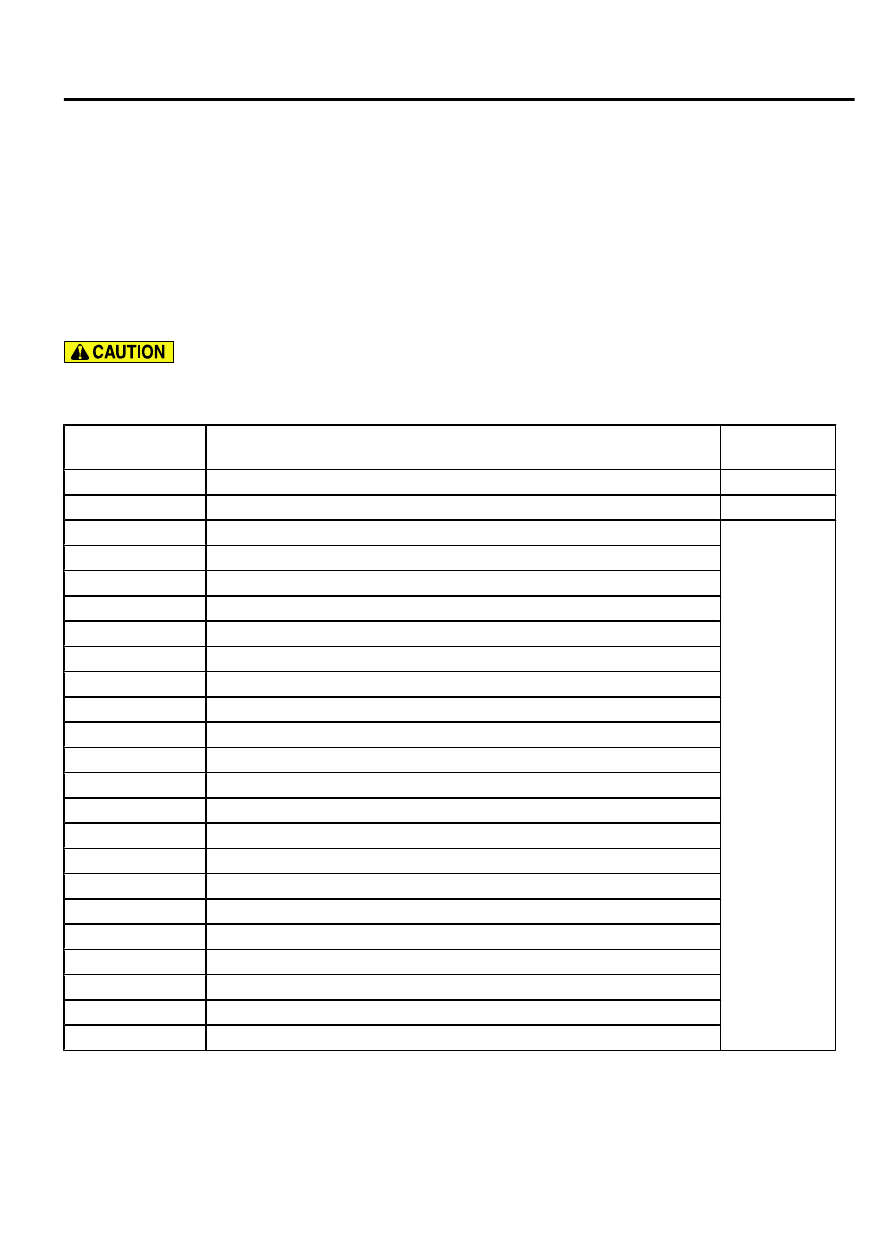
DIAGNOSTIC TROUBLE CODE CHART

M15504000049USA0000010000

During  diagnosis,  a  DTC  code  associated  with
another  system  may  be  set  when  the  ignition
switch

 is

 turned

 on

 with

 connector(s)

disconnected.  After  completing  the  repair,
confirm all systems for DTC code(s). If DTC code
(s) are set, erase them all.

Diagnostic
trouble code No.

Diagnostic item

Reference
page

B10C0

Interior temperature sensor system (short circuit)

 P.55B-8

B10C1

Interior temperature sensor system (open circuit)

 P.55B-8

B1000

Control panel communication error

Refer

 to

GRUOP  55A,
diagnostic
trouble  code
chart P.55A-8

B1003

Mode dial SW error

B1018

Temperature control dial SW error

B1021

Fan dial SW error

B1031

Air thermo sensor system (short circuit)

B1032

Air thermo sensor system (open circuit)

B1034

Ambient air temperature sensor system (short circuit)

B1035

Ambient air temperature sensor system (open circuit)

B1079

Refrigerant leaks

B2214

Control panel failure

B223B

Control panel improperly assembled

U1415

Coding not completed

U0019

Bus off (CAN1)

U0141

ETACS-ECU time-out

U0151

SRS-ECU time-out

U0154

Occupant classification-ECU time-out

U0155

Combination meter time-out

U0168

WCM time-out

U0184

Audio time-out

U0195

Satellite radio tuner time-out

U0197

Hands free module time-out

AUTOMATIC AIR CONDITIONING

55B-7

AUTO A/C DIAGNOSIS

DIAGNOSTIC TROUBLE CODE PROCEDURES

DTC B10C0, B10C1: Interior Temperature Sensor System

M15504000123USA0000010000

Interior Temperature Sensor Circuit

A/C-ECU

INTERIOR
TEMPERATURE
SENSOR

ZC6008760042

Connector: C-109, C-122

C-122

C-109 (B)

DTC SET CONDITION

DTC B10C0 is set if there is a short circuit in the
interior temperature sensor input circuit.

DTC B10C1 is set if there is a defective connector
connection,  or  if  there  is  an  open  circuit  in  the
harness.

TECHNICAL DESCRIPTION (COMMENT)

Current trouble

The A/C-ECU, the interior temperature sensor, or
connector(s)  or  wiring  between  the  two  may  be
defective.

Past trouble

If DTC B10C0 or B10C1 is stored as a past trouble,
carry  out  diagnosis  with  particular  emphasis  on
wiring and connector(s) between the A/C-ECU and
the  interior  temperature  sensor.  If  the  connectors
and wiring are normal, and obviously the ECU is the
cause of the trouble, replace the ECU. If in doubt,
do not replace the ECU.

TROUBLESHOOTING HINT

Malfunction of connector.

Malfunction of the harness.

Malfunction of the interior temperature sensor.

Malfunction of the A/C-ECU.

55B-8

AUTOMATIC AIR CONDITIONING

AUTO A/C DIAGNOSIS

DIAGNOSIS

Required Special Tool:

MB991958: Scan Tool (M.U.T.-III Sub Assembly)

MB991824: Vehicle Communication Interface (V.C.I.)

MB991827: M.U.T.-III USB Cable

MB991910:  M.U.T.-III  Main  Harness  A  (Vehicles  with
CAN communication system)

STEP 1. Using scan tool MB991958, diagnose the CAN bus
line.

ZC501967

AC404789

ZC5019680000

MB991824

MB991827

MB991910

Data link

connector

To prevent damage to scan tool MB991958, always turn the
ignition  switch  to  the  "LOCK"  (OFF)  position  before
connecting or disconnecting scan tool MB991958.
Use scan tool MB991958 to diagnose the CAN bus lines.

(1)

Connect scan tool MB991958. Refer to "How to connect the
Scan Tool (M.U.T.-III) P.55B-4."

(2)

Turn the ignition switch to "ON" position.

(3)

Diagnose the CAN bus line.

Q:Is the check result satisfactory?

YES:

 Go to Step 2.

NO:

 Repair the CAN bus lines. Repair the CAN bus lines

(Refer to GROUP 54D, Diagnosis-Can Bus Diagnostic
Chart P.54D-17).

STEP 2. Recheck for diagnostic trouble code.
Recheck if the DTC is set.

(1)

Erase the DTC.

(2)

Turn the ignition switch to "ON" position.

(3)

Check if the DTC is set.

Q:Is the check result satisfactory?

YES:

 It can be assumed that this malfunction is

intermittent. Refer to GROUP 00, How to Use
Troubleshooting/Inspection Service Points - How to Cope
with Intermittent Malfunctions P.00-15.

NO:

 Go to Step 3.

STEP 3. Check interior temperature sensor connector C-122
and A/C-ECU connector C-109 for loose, corroded or
damaged terminals, or terminals pushed back in the
connector.

Q:Are interior temperature sensor connector C-122 and A/

C-ECU connector C-109 in good condition?

YES:

 Go to Step 4.

AUTOMATIC AIR CONDITIONING

55B-9

AUTO A/C DIAGNOSIS

NO:

 Repair or replace the connector. Refer to GROUP 00E,

Harness Connector Inspection P.00E-2.

STEP 4. Check the wiring harness between A/C-ECU
connector C-109 (terminal 17 and 18) and interior
temperature sensor connector C-122 (terminals 1 and 2).

Q:Is the wiring harness between A/C-ECU connector C-109

(terminal  17  and  18)  and  interior  temperature  sensor

connector C-122 (terminals 1 and 2) in good condition?

YES:

 Go to Step 5.

NO:

 Repair the wiring harness.

STEP 5. Check the interior temperature sensor.

ZC602691

20

15

10

5

0

-10
(14)

0
(32)

20
(68)

10
(50)

30
(86)

40
(104)

RESISTANCE

TEMPERATURE °C (°F)

(k

W

)

Measure the resistance between connector terminals 1 and 2
under at least two different temperatures. The resistance values
should generally match those in the graph.

NOTE: 

The temperature at the check should not exceed the

range in the graph.

Q:Is the interior temperature sensor in good condition?

YES:

 Replace the A/C-ECU. Then go to Step 6.

NO:

 Replace the interior temperature sensor. Then go to

Step 6.

STEP 6. Recheck for diagnostic trouble code.
Check again if the DTC is set.

(1)

Connect scan tool MB991958 to the data link connector

(2)

Turn the ignition switch to the "ON" position.

(3)

Check if the DTC is set.

(4)

Turn the ignition switch to the "LOCK" (OFF) position.

Q:Is the check result satisfactory?

YES:

 The procedure is complete.

NO:

 Return to Step 1.

SYMPTOM CHART

M15504000050USA0000010000

During  diagnosis,  a  DTC  code  associated  with
another  system  may  be  set  when  the  ignition
switch

 is

 turned

 on

 with

 connector(s)

disconnected.  On  completion,  confirm  all
systems for DTC code(s). If DTC code(s) are set,
erase them all.

Symptom

Inspection
procedure

Reference
page

When the A/C is operation, temperature inside the passenger compartment
does not decrease (Cool air is not emitted).

1

Refer

 to

GRUOP  55A,
symptom
chart

 P.

55A-61

Malfunction of the A/C power supply system.

2

The compressor does not work.

3

Blower fan and motor do not turn.

4

Blower air amount cannot be changed.

5

Outside/inside air changeover is not possible.

6

A/C outlet air temperature does not increase.

7

55B-10

AUTOMATIC AIR CONDITIONING

AUTO A/C DIAGNOSIS


Content   ..  1209  1210  1211  1212   ..