Content .. 1076 1077 1078 1079 ..
Mitsubishi Outlander XL. Manual - part 1078
ZC501967
AC404789
ZC5019680000
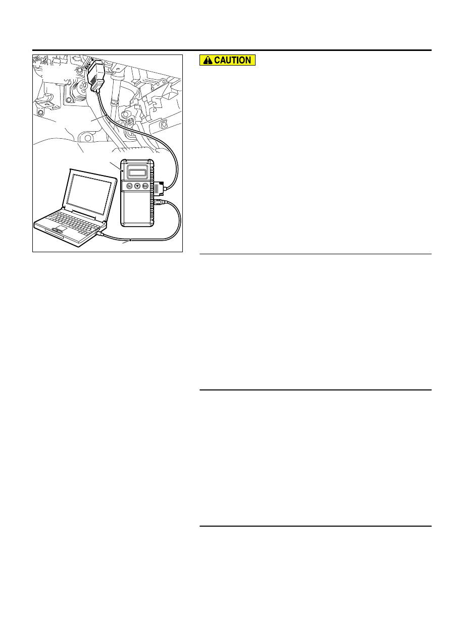
MB991824
MB991827
MB991910
Data link
connector
To prevent damage to scan tool MB991958, always turn the
ignition switch to the "LOCK" (OFF) position before
connecting or disconnecting scan tool MB991958.
(1)
Connect scan tool MB991958. Refer to "How to connect scan
tool P.54Ah-4."
(2)
Turn the ignition switch to the "ON" position.
(3)
Erase the DTC.
(4)
Turn the ignition switch from "LOCK" (OFF) position to "ON"
position.
(5)
Check if the DTC B2350 or B2351 is set.
(6)
Turn the ignition switch to the "LOCK" (OFF) position.
Q:Is the DTC set?
DTC B2351 is set.:
Go to Step 2.
DTC B2350 is set.:
Go to Step 3.
No DTC is set.:
The trouble can be an intermittent
malfunction (GROUP 00 - How to Cope with Intermittent
Malfunction P.00-15).
STEP 2. Using scan tool MB991958, Check whether the
diagnostic trouble code is reset.
Check again if the DTC is set to the ETACS-ECU.
(1)
Replace the wiper/washer switch.
(2)
Turn the ignition switch to the "ON" position.
(3)
Erase the DTC.
(4)
Turn the ignition switch from "LOCK" (OFF) position to "ON"
position.
(5)
Check if DTC is set.
(6)
Turn the ignition switch to the "LOCK" (OFF) position.
Q:Is the DTC set?
YES:
Go to Step 3.
NO:
The procedure is complete.
STEP 3. Using scan tool MB991958, Check whether the
diagnostic trouble code is reset.
Check again if the DTC is set to the ETACS-ECU.
(1)
Replace the lighting switch.
(2)
Turn the ignition switch to the "ON" position.
(3)
Erase the DTC.
(4)
Turn the ignition switch from "LOCK" (OFF) position to "ON"
position.
(5)
Check if DTC is set.
(6)
Turn the ignition switch to the "LOCK" (OFF) position.
Q:Is the DTC set?
YES:
Go to Step 4.
NO:
The procedure is complete.
STEP 4. Using scan tool MB991958, Check whether the
diagnostic trouble code is reset.
Check again if the DTC is set to the ETACS-ECU.
(1)
Turn the ignition switch to the "ON" position.
COLUMN SWITCH
54Ah-7
DIAGNOSIS