Mitsubishi Outlander GS45X. Manual - part 572
MULTIPORT FUEL INJECTION (MFI) DIAGNOSIS
TSB Revision
MULTIPORT FUEL INJECTION (MFI) <2.4L ENGINE>
13A-111
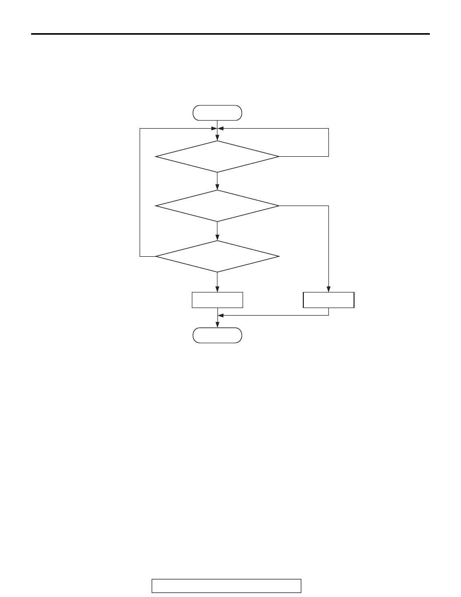
DTC SET CONDITIONS
Logic Flow Chart
.
Check Conditions
• More than 220 seconds have passed since the
engine starting sequence was completed.
• While the linear air-fuel ratio sensor heater is on.
• Battery positive voltage is between 11 and 16.5
volts.
• Intake air temperature is more than −10°C (14°F).
• On duty cycle of the linear air-fuel ratio sensor
heater is between 3 and 97 percent.
Judgement Criterion
• The linear air-fuel ratio sensor heater current has
continued to be lower than average 1.25 ampere
for 10 seconds.
.
OBD-II DRIVE CYCLE PATTERN
• Refer to Diagnostic Function − OBD-II Drive
Cycle
− Pattern 22
.
.
TROUBLESHOOTING HINTS (The most
likely causes for this code to be set are:)
• Linear air-fuel ratio sensor circuit harness dam-
age or connector damage.
• Linear air-fuel ratio sensor heater failed.
• ECM failed.
End
No
No
No
Malfunction
Good
Heater current
< 1.25 A
AK900351
Start
Yes
Yes
Yes
Continuous
failure for 10secs
Monitoring
conditions