Mitsubishi Outlander GS45X. Manual - part 570


  Index      Mitsubishi     Mitsubishi Outlander GS45X - service repair manual


Search            


Content   ..  568  569  570  571   ..


Mitsubishi Outlander GS45X. Manual - part 570


MULTIPORT FUEL INJECTION (MFI) DIAGNOSIS

TSB Revision

MULTIPORT FUEL INJECTION (MFI) <2.4L ENGINE>

13A-103

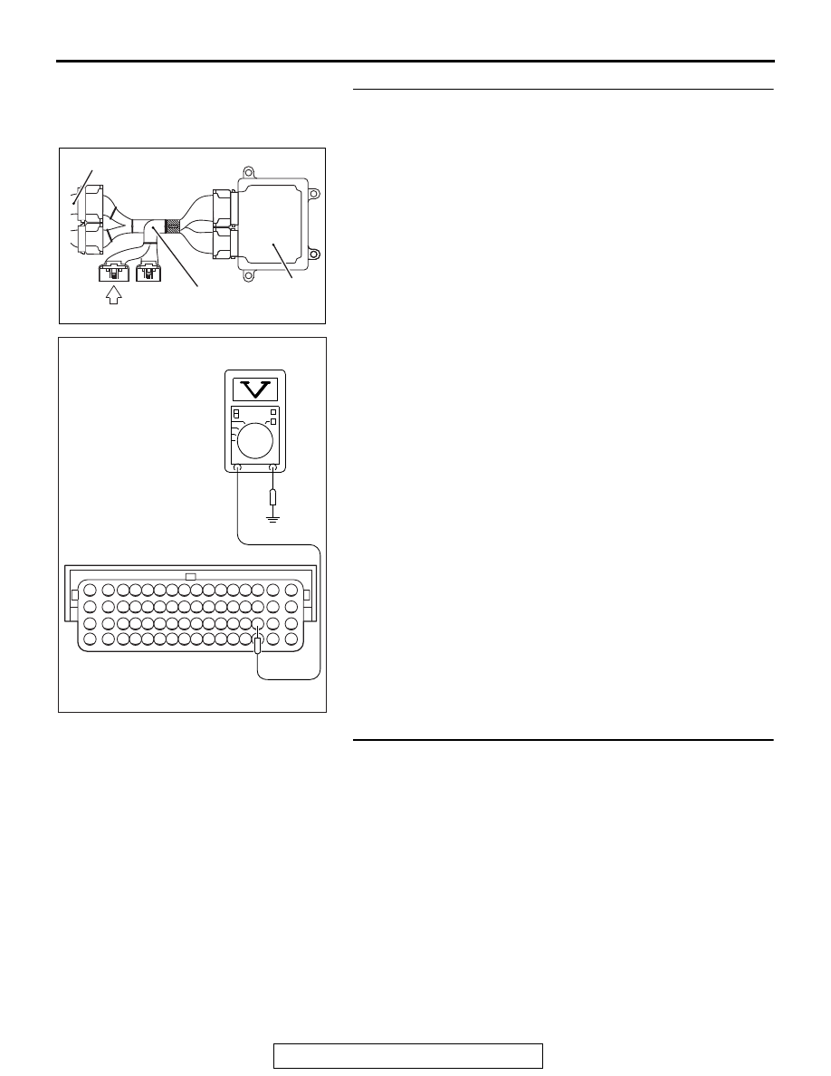
STEP 6. Measure the power supply voltage at ECM 
connector B-10 by using power plant ECU check harness 
special tool MB992110.
(1) Disconnect all ECM connectors. Connect the power plant 

ECU check harness special tool MB992110 between the 
separated connectors.

(2) Turn the ignition switch to the "ON" position.

(3) Measure the voltage between terminal No. 35 and ground.

• Voltage should be battery positive voltage.

(4) Turn the ignition switch to the "LOCK" (OFF) position.
Q: Is battery positive voltage (approximately 12 volts) 

present?
YES : 
Go to Step 8.
NO :  Go to Step 7.

STEP 7. Check for open circuit and short circuit to ground 
between heated oxygen sensor (rear) connector D-37 
(terminal No. 2) and ECM connector B-10 (terminal No. 35).
NOTE: Check harness after checking intermediate connectors 
C-129 and A-13. If intermediate connectors are damaged, 
repair or replace it. Refer to GROUP 00E, Harness Connector 
Inspection 

P.00E-2

. Then go to Step 11.

Q: Is the harness wire in good condition?

YES : Replace the ECM. When the ECM is replaced, 

register the ID code. Refer to GROUP 42B, Diagnosis 
− ID Code Registration Judgment Table <Vehicles 

with KOS> 

P.42B-15

 or GROUP 42C, Diagnosis 

− ID 

Codes Registration Judgment Table <Vehicles with 
WCM> 

P.42C-10

. Then go to Step 11.

NO :  Repair it. Then go to Step 11.

AK604040

ECM

AB

Body side harness 

MB992110

AK604174

16 15 14 13 12 11 10 9 8 7 6 5 4 3

2

1

32 31 30 29 28 27 26 25 24 23 22 21 20 19 18 17

48 47 46 45 44 43 42 41 40 39 38 37 36 35 34 33

64 63 62 61 60 59 58 57 56 55 54 53 52 51 50 49

AB

Power plant ECU
check harness connector

MULTIPORT FUEL INJECTION (MFI) DIAGNOSIS

TSB Revision

MULTIPORT FUEL INJECTION (MFI) <2.4L ENGINE>

13A-104

STEP 8. Check for harness damage between MFI relay 
connector A-33X (terminal No. 2) and heated oxygen 
sensor (rear) connector D-37 (terminal No. 1).
NOTE: Check harness after checking intermediate connector 
C-129. If intermediate connector is damaged, repair or replace 
it. Refer to GROUP 00E, Harness Connector Inspection 

P.00E-2

. Then go to Step 11.

Q: Is the harness wire in good condition?

YES : Go to Step 9.
NO :  Repair it. Then go to Step 11.

STEP 9. Check for harness damage between heated 
oxygen sensor (rear) connector D-37 (terminal No. 2) and 
ECM connector B-10 (terminal No. 35).
NOTE: Check harness after checking intermediate connectors 
C-129 and A-13. If intermediate connectors are damaged, 
repair or replace it. Refer to GROUP 00E, Harness Connector 
Inspection 

P.00E-2

. Then go to Step 11.

Q: Is the harness wire in good condition?

YES : Go to Step 10.
NO :  Repair it. Then go to Step 11.

STEP 10. Check the trouble symptoms.
(1) Carry out a test drive with the drive cycle pattern. Refer to 

Diagnostic Function 

− OBD-II Drive Cycle − Pattern 2 

P.13A-11

.

(2) Check the diagnostic trouble code (DTC).
Q: Is DTC P0037 set?

YES : Replace the ECM. When the ECM is replaced, 

register the ID code. Refer to GROUP 42B, Diagnosis 
− ID Code Registration Judgment Table <Vehicles 

with KOS> 

P.42B-15

 or GROUP 42C, Diagnosis 

− ID 

Codes Registration Judgment Table <Vehicles with 
WCM> 

P.42C-10

. Then go to Step 11.

NO :  It can be assumed that this malfunction is intermittent. 

Refer to GROUP 00, How to Use 
Troubleshooting/Inspection Service Points 

− How to 

Cope with Intermittent Malfunctions 

P.00-15

STEP 11. Test the OBD-II drive cycle.
(1) Carry out a test drive with the drive cycle pattern. Refer to 

Diagnostic Function 

− OBD-II Drive Cycle − Pattern 2 

P.13A-11

.

(2) Check the diagnostic trouble code (DTC).
Q: Is DTC P0037 set?

YES : Retry the troubleshooting.
NO :  The inspection is complete.

MULTIPORT FUEL INJECTION (MFI) DIAGNOSIS

TSB Revision

MULTIPORT FUEL INJECTION (MFI) <2.4L ENGINE>

13A-105

DTC P0038: Heated Oxygen Sensor (rear) Heater Control Circuit High

AK704091

1

3

2

4

2

8

7

6

5

4

3

11

21

20

19

18

17

16

15

14

13

12

9

22

1

10

1 2

3 4

1

10 111213 14 1516 17 1819 20

2 3 4

5 6 7 8 9

1

2

3 4 5 6 7 8 9 10 11 12 13 14 15 16

17 18 19 20 21 22 23 24 25 26 27 28 29 30 31 32

33 34 35 36 37 38 39 40 41 42 43 44 45 46 47 48

49 50 51 52 53 54 55 56 57 58 59 60 61 62 63 64

WHITE

WHITE

HEATED OXYGEN SENSOR (REAR) HEATER CIRCUIT 

36

FUSIBLE LINK

AE

D-37

19

20A

WHITE

A-33X

4

3

1

2

22

C-129

B-10

OFF

ON

1

4

2

3

WHITE

16

1

A-13

35

HEATED OXYGEN SENSOR
(REAR)

RELAY BOX
(ENGINE COMPARTMENT)

ENGINE
CONTROL
MODULE

TO ECM

TO ECM

TO ECM

MFI
RELAY

BR

O

W

N

BR

O

W

N

BR

O

W

N

MULTIPORT FUEL INJECTION (MFI) DIAGNOSIS

TSB Revision

MULTIPORT FUEL INJECTION (MFI) <2.4L ENGINE>

13A-106

.

CIRCUIT OPERATION

• Power is supplied from the MFI relay (terminal 

No. 2) to the heated oxygen sensor (rear) heater.

• The ECM (terminal No. 35) controls continuity to 

the heated oxygen sensor (rear) heater by turn-
ing the power transistor in the ECM "ON" and 
"OFF".

.

TECHNICAL DESCRIPTION

• The ECM checks whether the heater current is 

within a specified range when the heater is ener-
gized.

.

DESCRIPTIONS OF MONITOR METHODS

Heated oxygen sensor heater (rear) current is out of 

specified range.

.

MONITOR EXECUTION

Continuous

.

MONITOR EXECUTION CONDITIONS 
(Other monitor and Sensor)

Other Monitor (There is no temporary DTC stored 

in memory for the item monitored below)

• Not applicable

Sensor (The sensor below is determined to be 

normal)

• Not applicable

.

AK704087AB

Connector: A-13

A-13

AK704088

MFI relay

AB

Connector: A-33X

A-33X

AK704090AB

Connector: B-10

B-10 (GR)

AK900595

Connector: C-129

C-129

AB

AK900665

D-37 (B)

Rear heater duct (RH)

Heated oxygen 
sensor (rear) 

AB

Connector: D-37


Content   ..  568  569  570  571   ..