Mitsubishi Outlander GS45X. Manual - part 571
MULTIPORT FUEL INJECTION (MFI) DIAGNOSIS
TSB Revision
MULTIPORT FUEL INJECTION (MFI) <2.4L ENGINE>
13A-107
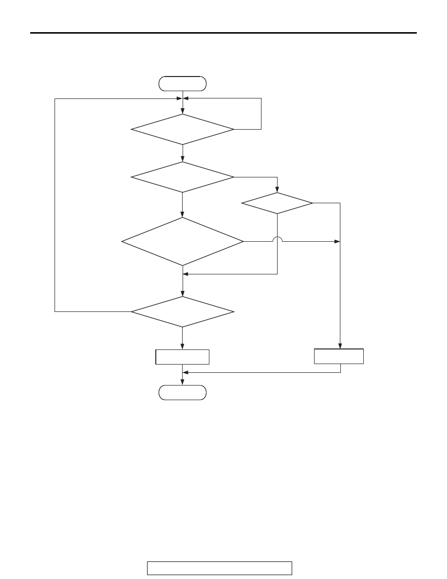
DTC SET CONDITIONS
Logic Flow Chart
.
Check Conditions
• More than 2 seconds have passed since the
engine starting sequence was completed.
• While the heated oxygen sensor (rear) heater is
on.
• Battery positive voltage is between 11 and 16.5
volts.
Judgement Criterion
• The heated oxygen sensor (rear) heater current
has continued to be higher than 10.5 amperes for
2 seconds.
.
OBD-II DRIVE CYCLE PATTERN
• Refer to Diagnostic Function − OBD-II Drive
Cycle
− Pattern 2
.
TROUBLESHOOTING HINTS (The most
likely causes for this code to be set are:)
• Heated oxygen sensor (rear) failed.
• ECM failed.
End
No
No
Malfunction
Good
Current < 0.17A
or
Current > 10.5A
Voltage < 2.0V
AK900352
Heater activation
command ON
No
No
Start
Yes
Yes
Yes
Yes
Yes
No
Continuous
failure for 2secs
Monitoring
conditions