Mitsubishi Outlander GS45X. Manual - part 505


  Index      Mitsubishi     Mitsubishi Outlander GS45X - service repair manual


Search            


Content   ..  503  504  505  506   ..


Mitsubishi Outlander GS45X. Manual - part 505


TIMING BELT

TSB Revision

ENGINE MECHANICAL <3.0L ENGINE>

11C-57

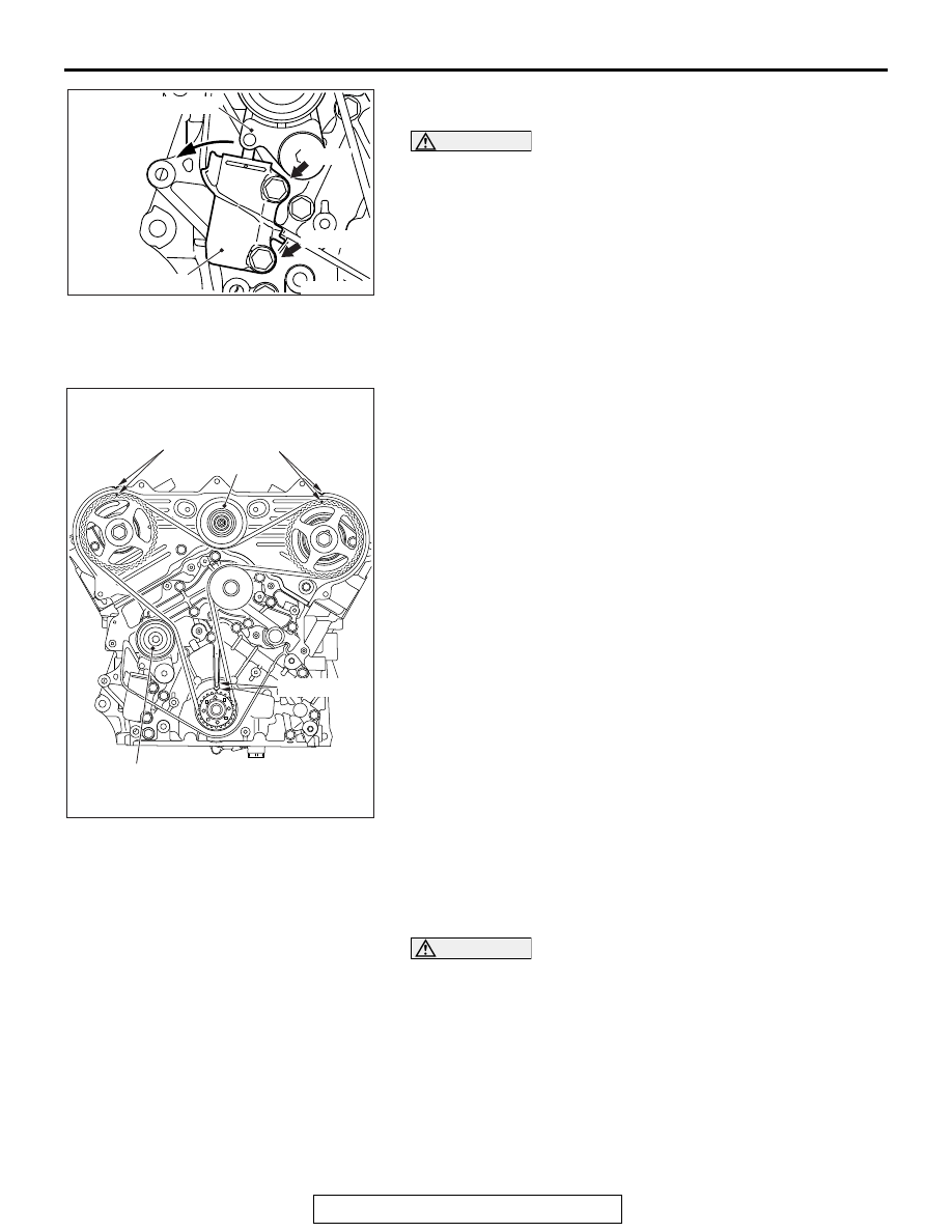
2. Remove the upper mounting bolt of the timing belt 

auto-tensioner.

CAUTION

The timing belt auto-tensioner rotates centering on the 
flange bolt due to the rod thrust, so please make sure your 
finger is not trapped.
3. Loosen the lower mounting bolt of the timing belt 

auto-tensioner slowly and slide the timing belt 
auto-tensioner slightly. Remove the rod from the tensioner 
arm.

4. Remove the lower mounting bolt of the timing belt 

auto-tensioner.

.

<<B>> TIMING BELT REMOVAL

1. Check that the timing marks of each sprocket are aligned.
2. If the timing belt is to be reused, chalk an arrow on the flat 

side of the belt, indicating the clockwise direction.

3. Loosen the center bolt of the tensioner pulley, then remove 

the timing belt.

INSTALLATION SERVICE POINT

.

>>A<< TIMING BELT/TIMING BELT AUTO-TEN-
SIONER INSTALLATION

CAUTION

Always bleed the timing belt auto-tensioner of air before 
installing the timing belt auto-tensioner (Refer to 

P.11C-59

).

1. Insert the pin into the rod of the auto-tensioner under the 

following procedures.

AC703074

Auto-tensioner

Tensioner arm

Upper

Lower

AB

AC703035

Timing mark

Timing mark

Idler pulley

Timing mark

Tension pulley

AB

TIMING BELT

TSB Revision

ENGINE MECHANICAL <3.0L ENGINE>

11C-58

CAUTION

Notable factors for inserting pin

• Always use the vertical press and put the auto-ten-

sioner vertically.

• Do not apply the load of 5,000 N (1,124 pound) or more 

to the rod. 

• Do not press the rod beyond the dimension shown in 

the illustration.

(1) Put the auto-tensioner vertically to the vertical press not 

to be in the sideways direction.

(2) Slowly close the vice to force the rod in until the hole (A) 

of the rod is lined up with set hole (B) of the cylinder.

(3) Insert a pin into the set holes.
(4) Remove the timing belt auto-tensioner from the vice.

2. Install the timing belt auto-tensioner with the setting pin, and 

tighten the mounting bolts to the specified torque.

Tightening torque: 23 

± 6 Nm (17 ± 4 ft-lb)

3. Align the timing marks on the camshaft sprockets with those 

on the timing belt rear cover and the timing mark on the 
crankshaft sprocket with that on the engine block as shown 
in the illustration.

AC703075

Upright
stance

Under 5,000 N
(1,124 lb)

3 mm (0.12 in)

AB

AC703037

Pin hole A

Pin hole B

AB

AC703076

Camshaft sprocket

Timing marks

<Right bank>

<Left bank>

AB

AC703077

Timing mark

Timing mark

Camshaft sprocket

AB

TIMING BELT

TSB Revision

ENGINE MECHANICAL <3.0L ENGINE>

11C-59

CAUTION

The camshaft sprocket (right bank) can turn easily due to 
the spring force applied, so be careful not to get your fin-
gers caught.
4. Install the timing belt by the following procedure so that 

there is no deflection in the timing belt between each 
sprocket and pulley.

(1) Crankshaft sprocket
(2) Water pump pulley
(3) Camshaft sprocket (Left bank)
(4) Idler pulley
(5) Camshaft sprocket (Right bank)
(6) Tensioner pulley

5. Apply the force to the camshaft sprocket (Right bank) 

counterclockwise until the tension side of timing belt is tight. 
Check all the timing marks again.

6. Remove the setting pin that has been inserted into the 

auto-tensioner.

7. Turn the crankshaft clockwise twice to align the timing 

marks.

8. Wait for at least five minutes, then check that the 

auto-tensioner push rod extends within the standard value 
range.

Standard value (A): 9.1 

 13.4 mm (0.36  0.52 inch)

9. If not, repeat the operation in steps 1 to 8 above.
10.Check again that the timing marks of the sprockets are 

aligned.

INSPECTION

M1112004400965

.

TIMING BELT AUTO-TENSIONER CHECK

1. Check for oil leak from seal, and replace it if leak is detected.
2. Check for wear or damage at the top of the rod. Replace it, if 

required.

.

AC703035

Timing mark

Timing mark

Idler pulley

Timing mark

Tension pulley

AC

AC703036

A

AB

TIMING BELT

TSB Revision

ENGINE MECHANICAL <3.0L ENGINE>

11C-60

AIR BLEEDING METHOD

CAUTION

• Always use the vertical press and put the auto-ten-

sioner vertically.

• Do not apply the load of 5,000 N (1,124 pound) or more 

to the rod.

• Do not press the rod beyond Dimension "A" shown in 

the illustration.

1. Set the auto-tensioner as shown in the illustration.
2. Press the rod slowly down to the lowest point "A" shown in 

the illustration.

3. Repeat the procedure 2 three times.
4. While the rod is projected at the point "B" shown in the 

illustration, push the rod with 100 

− 200 N (22 − 44 pound). 

Check the enough stiffness. If the stiffness is not enough, 
replace the auto-tensioner.

5. Press down the rod slowly. Put the pin through the hole and 

secure it.

AC703078

A: 3 mm 
 (0.12 in)

B: 11.4 mm 
(0.45 in)

Under 5,000 N
(1,124 lb)

100 to 200 N
(22 to 44 lb)

Upright
stance

AB


Content   ..  503  504  505  506   ..