Mitsubishi Outlander GS45X. Manual - part 504


  Index      Mitsubishi     Mitsubishi Outlander GS45X - service repair manual


Search            


Content   ..  502  503  504  505   ..


Mitsubishi Outlander GS45X. Manual - part 504


CYLINDER HEAD GASKET

TSB Revision

ENGINE MECHANICAL <3.0L ENGINE>

11C-53

INSTALLATION SERVICE POINTS

.

>>A<< CYLINDER HEAD ASSEMBLY INSTALLA-
TION

CAUTION

Be careful that no foreign material gets into the cylinder, 

coolant passages or oil passages. Engine damage may 

result.
1. Use a scraper to clean the gasket surface of the cylinder 

head assembly.

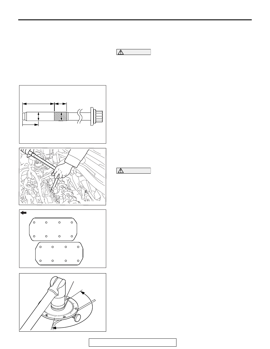
2. Check in the following procedure before reusing the cylinder 

head bolt.

(1) Measure the outside diameter "A".
(2) Measure the smallest outside diameter "B" within the 

range "X" shown in the illustration.

(3) If the difference of outside diameter of thread exceeds 

the limit, replace the cylinder head bolt.

Limit: 0.1mm (0.0039 inch)

3. Tighten the bolts to the specified torque in the order shown 

in the illustration. (in two or three cycles)

Tightening torque: 45 

± 2 Nm (33 ± 1 ft-lb)

CAUTION

• If the bolt is turned less than 150 to 154 degrees, proper 

fastening performance may not be achieved. Be sure to 
turn the bolt exactly 150 to 154 degrees.

• If the bolt is overtightened, loosen the bolt completely 

and then retighten it by repeating the tightening proce-
dure from step 1.

4. Using special tool MB991614, tighten the cylinder head bolt 

another 150 to 154 degrees.

AK700001AB

34 mm
(1.34 in)

17 mm
(0.67 in)

A

B

B

X

AC703060AB

AC703072

Engine front

<Right
bank>

<Left
bank>

1

2

3

4

5

6

7

8

1

2

3

4

5

6

7

8

AC

AC703073

150˚ to 154˚

MB991614

AB

CYLINDER HEAD GASKET

TSB Revision

ENGINE MECHANICAL <3.0L ENGINE>

11C-54

.

>>B<< CAMSHAFT SPROCKET INSTALLATION

1. Use special tools MB990767 and MD998719 in the same 

way as during removal to hold the camshaft sprocket.

2. Tighten the camshaft sprocket mounting bolt to the specified 

torque.

Tightening torque: 90 

± 10 Nm (66 ± 7 ft-lb)

AC703052

MB990767

MD998719

AB

TIMING BELT

TSB Revision

ENGINE MECHANICAL <3.0L ENGINE>

11C-55

TIMING BELT

REMOVAL AND INSTALLATION

M1112004302629

Pre-removal operation
• Engine Cover Removal (Refer to GROUP 16, Ignition 

System 

− Ignition Coil 

P.16-49

).

• Engine Room Under Cover Front B and Engine Room 

Side Cover (RH) Removal (Refer to GROUP 51, Under 

Cover 

P.51-23

).

• Crankshaft Pulley Removal (Refer to 

P.11C-23

).

Post-installation operation
• Crankshaft Pulley Installation (Refer to 

P.11C-23

).

• Engine Room Under Cover Front B and Engine Room 

Side Cover (RH) Installation (Refer to GROUP 51, Under 

Cover 

P.51-23

).

• Engine Cover Installation (Refer to GROUP 16, Ignition 

System 

− Ignition Coil 

P.16-49

).

AC605911

AE

2

9

1

3

5

7

4

6

8

23 ± 6 N·m
17 ± 4 ft-lb

6.5 ± 1.5 N·m
58 ± 13 in-lb

6.5 ± 1.5 N·m
58 ± 13 in-lb

6.5 ± 1.5 N·m
58 ± 13 in-lb

23 ± 6 N·m
17 ± 4 ft-lb

41 ± 10 N·m
30 ± 8 ft-lb

20 ± 5 N·m
15 ± 3 ft-lb

48 ± 11 N·m
36 ± 8 ft-lb

6.5 ± 1.5 N·m
58 ± 13 in-lb

Removal steps 

1.

Auto-tensioner

2.

Timing belt front upper cover, right

3.

Timing belt front upper cover, left

4.

Timing belt lower cover

Engine mounting bracket (Refer to 
GROUP 32, Engine Mounting 

P.32-5

)

5.

Engine support bracket

6.

Front flange

<<

A

>> >>

A

<< 7.

Timing belt auto-tensioner

<<

B

>> >>

A

<< 8.

Timing belt

9.

Tensioner pulley assembly

Removal steps (Continued)

TIMING BELT

TSB Revision

ENGINE MECHANICAL <3.0L ENGINE>

11C-56

Required Special Tools:

• MB990767: Front Hub and Flange Yoke Holder

• MD998716: Crankshaft Wrench

• MD998719: Pin

REMOVAL SERVICE POINTS

.

<<A>> TIMING BELT AUTO-TENSIONER 
REMOVAL

CAUTION

Never turn the crankshaft counterclockwise.
1. Use special tool MD998716 to turn the crankshaft clockwise 

to align each timing mark and to set the No. 1 cylinder to 
compression top dead center.

AC703061

MD998716

AB

AC703035

Timing mark

Timing mark

Idler pulley

Timing mark

Tension pulley

AB


Content   ..  502  503  504  505   ..