Mitsubishi Outlander GS45X. Manual - part 465
HYDRAULIC UNIT
TSB Revision
ACTIVE STABILITY CONTROL SYSTEM (ASC)
35C-287
HYDRAULIC UNIT
REMOVAL AND INSTALLATION
M1355005600572
CAUTION
When the hydraulic unit (integrated with ASC-ECU) is replaced, after turning the ignition switch ON or
OFF (vehicle information from ETACS-ECU is registered), always carry out the calibration of all sen-
sors (steering wheel sensor, G and yaw rate sensor, and brake fluid pressure sensor) at one time.(
Refer to
.)
Pre-removal operation
• Strut tower bar removal (Refer to GROUP 42A − Strut
Tower Bar
.)
• Brake fluid draining
• Intake manifold plenum removal (Refer to GROUP 15 −
Intake Manifold Plenum
Post-installation operation
• Intake manifold plenum installation (Refer to GROUP 15 −
Intake Manifold Plenum
• Brake fluid refilling and air bleeding (Refer to GROUP 35A
− On-vehicle Service, Brake Fluid Level Inspection and
Bleeding
• Strut tower bar installation (Refer to GROUP 42A − Strut
Tower Bar
.)
• Hydraulic unit check (Refer to
AC703833 AB
5
1
11
5
10 ± 2 N·m
89 ± 17 in-lb
24 ± 4 N·m
18 ± 3 ft-lb
5
9
12
16 ± 3 N·m
12 ± 2 ft-lb
5
10
13 ± 2 N·m
111 ± 22 in-lb
3
8
4
5
2
6
7
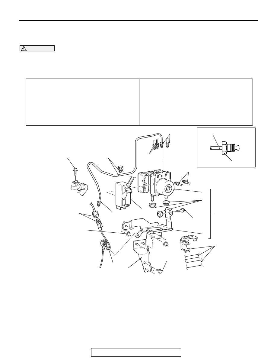
Removal steps
1.
ASC-ECU harness connector
2.
Suction pipe installation bolt
3.
Wheel speed sensor harness
connector connection
4.
Wheel speed sensor harness clip
connection
>>A<<
5.
Brake tube connection
6.
Brake tube and clip connection
7.
Suction pipe, liquid pipe and clip
connection
8.
Hydraulic unit (ASC-ECU) and
hydraulic unit bracket
<<A>>
9.
Hydraulic unit (ASC-ECU)
10. Hydraulic unit bracket insulator
11. Hydraulic unit bracket B
12. Hydraulic unit bracket A
Removal steps (Continued)