Mitsubishi Outlander GS45X. Manual - part 463


  Index      Mitsubishi     Mitsubishi Outlander GS45X - service repair manual


Search            


Content   ..  461  462  463  464   ..


Mitsubishi Outlander GS45X. Manual - part 463


ON-VEHICLE SERVICE

TSB Revision

ACTIVE STABILITY CONTROL SYSTEM (ASC)

35C-279

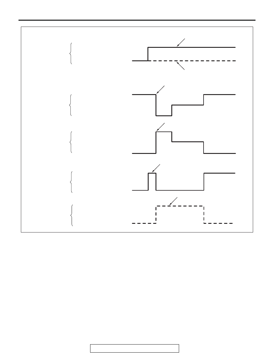
5. This is indicated as shown in the above.
6. When any malfunction has been found, take a necessary 

action according to the "Judgment Table."

AC400780AB

Scan tool actuator test
(No.01, 02, 03, 04) start

Scan tool actuator test
(No.05, 06, 07, 08) start

Scan tool actuator test
(No.01, 02, 03, 04)

Scan tool actuator test
(No.05, 06, 07, 08)

Scan tool actuator test
(No.05, 06, 07, 08)

Scan tool actuator test
(No.01, 02, 03, 04)

Pedal operation

Depressed

Released

Solenoid valve position

Increase in pressure

Steady pressure

Reduction in pressure

Increase in pressure

Steady pressure

Reduction in pressure

Cut valve, suction valve
position

Checking the brake force

Checking the brake force

Lock

When the pedal is free

Those with a braking effort

Those without a braking effort

Approx.
1 seconds

Approx.
1 seconds

Approx.
2 seconds

Approx.
2 seconds

Approx.
3 seconds

Approx.
3 seconds

ON-VEHICLE SERVICE

TSB Revision

ACTIVE STABILITY CONTROL SYSTEM (ASC)

35C-280

Judgment Table

7. After the inspection, turn the ignition switch to the LOCK 

(OFF) position, and then disconnect scan tool.

.

HYDRAULIC UNIT INSTALLATION ADJUSTMENT

Refer to 

P.35C-287

.

1. Operate the pre-removal steps for the hydraulic unit.
2. Remove all brake tubes.
3. Remove the protector.
4. Loosen the mounting bolt and nut of the hydraulic unit 

bracket.

5. Install all brake tubes temporarily.
6. Shake hydraulic unit to all directions with both hands to 

make the hydraulic unit bracket insulator fit with the unit.

Display on 
scan tool

Operation

Test result

Judgme
nt

Cause

Measure

01 FL wheel 
ABS
02 FR wheel 
ABS
03 RL wheel 
ABS
04 RR wheel 
ABS

• Depress the brake 

pedal to lock the 
wheel.

• Select the vehicle 

to be inspected 
using scan tool, 
perform the 
actuator test.

• Rotate the selected 

wheel by hands to 
confirm the braking 
force.

Braking force 
decreases for 3 
seconds from 
the lock status.

Normal

The wheel 
does not lock 
even if the 
brake pedal is 
depressed.

Error

Clogged brake line 
other than hydraulic 
unit

Check and 
clean the brake 
line.

Clogged hydraulic 
circuit in the hydraulic 
unit

Replace the 
hydraulic unit 
assembly.

Braking force 
does not 
decrease.

Faulty routing of 
hydraulic unit brake 
tube

Route the 
brake tube 
correctly.

Malfunction of 
hydraulic unit solenoid 
valve operation

Replace the 
hydraulic unit 
assembly.

05 FL wheel 
TCL
06 FR wheel 
TCL
07 RL wheel 
TCL
08 RR wheel 
TCL

• Select the vehicle 

to be inspected 
using scan tool, 
perform the 
actuator test.

• Rotate the selected 

wheel by hands to 
confirm the braking 
force.

Lock condition 
occurs for 3 
seconds from 
the status 
without braking 
force.

Normal

The wheel 
does not lock.

Error

• Faulty routing of 

hydraulic unit brake 
tube

• Clogged brake line 

other than hydraulic 
unit

Check and 
clean the brake 
line.

Clogged hydraulic 
circuit in the hydraulic 
unit

Replace the 
hydraulic unit 
assembly.

ON-VEHICLE SERVICE

TSB Revision

ACTIVE STABILITY CONTROL SYSTEM (ASC)

35C-281

7. Install the hydraulic unit bracket with mounting bolt and nut 

not to load the brake tube.

8. Install the protector.
9. Install all brake tubes securely.

NOTE: Install the flare nut taking care not to let the brake 
tube turn together.

10.Operate the post-installation steps of the hydraulic unit.

IN THE EVENT OF A DISCHARGED BATTERY

M1355006200168

WARNING

If the ASC is not operating, the vehicle will be unsta-
ble during braking, Do not drive the vehicle with the 
ASC-ECU connector disconnected or with the ASC 
not operating.

If the engine is started using a booster cable when the battery 
is completely flat, and the vehicle is then driven without waiting 
for the battery to be recharged, the engine may misfire and it 
may not be possible to drive the vehicle. This is because the 
ASC consumes a large amount of current when carrying out its 
initial checks. If this happens, recharge the battery fully.

ALL SENSOR CALIBRATION (G AND YAW RATE 
SENSOR, STEERING WHEEL SENSOR, BRAKE 
FLUID PRESSURE SENSOR)

M1357003900012

CAUTION

Before carrying out the calibration, check that the diagnos-
tic trouble code related to the steering wheel sensor, G and 
yaw rate sensor, or brake fluid pressure sensor is not set.

CAUTION

When the next operation has been completed, carry out 
the calibration to make ASC-ECU learn the neutral point of 
the steering wheel sensor, G and yaw rate sensor, and 
brake fluid pressure sensor.

• ASC-ECU replacement

CAUTION

Carry out the calibration under the following conditions.

• The vehicle has one occupant (driver) only.
• Turn the steering wheel to set the wheels in the 

straight-ahead positions. 

• The brake pedal is not depressed. (The stop light 

switch is OFF.)

1. Park the vehicle on a level surface.

CAUTION

Before connecting or disconnecting scan tool, always turn 
the ignition switch to the LOCK (OFF) position.
2. Before setting scan tool, turn the ignition key to the LOCK 

(OFF) position.

3. Turn the ignition switch to the ON position.

ON-VEHICLE SERVICE

TSB Revision

ACTIVE STABILITY CONTROL SYSTEM (ASC)

35C-282

4. Select "ABS/ASC/ASTC."
5. Select "Special function."
6. Select "Sensor calibration."
7. Select "all sensor calibration."
8. Before removing scan tool from the vehicle, turn the ignition 

key to the LOCK (OFF) position.

G AND YAW RATE SENSOR CALIBRATION

M1355009300175

CAUTION

Before performing calibration, check that the G and yaw 
rate sensor-related diagnosis code is not set.

CAUTION

After the next operation has been completed, carry out the 
calibration to make ASC-ECU learn the neutral position of 
the G and yaw rate sensor.

• G and yaw rate sensor replacement
• ASC-ECU replacement

1. Park the vehicle on a level surface.

CAUTION

Before connecting or disconnecting the scan tool, turn the 
ignition switch to the "LOCK" (OFF) position.
2. Set the scan tool with the ignition "LOCK" (OFF).
3. Turn the ignition switch to the ON position.
4. Select the relevant system from the menu.
5. Select "ABS/ASC/ASTC" from the system lists in "System 

select", and press "OK" button.

6. Select "Special function" in "ABS/ASC/ASTC".
7. Select "Sensor calibration" in "Special function".
8. Select "G sensor calibration" from the selected item, and 

press "OK" button.

9. The screen displays "G sensor calibration: The selected 

command will be executed. Are you sure? Caution: Please 
check the execution conditions." Then press "OK" button.

10."Execute: The command was executed." will be shown. 

Then press "OK" button.

11.Select "Lateral/G sensor calibration" from the selected item, 

and press "OK" button.

12.The screen displays "Lateral/G sensor calibration: The 

selected command will be executed. Are you sure? Caution: 
Please check execution conditions." Then press "OK" 
button.

13."Executed: The command was executed." will be shown. 

Then press "OK" button.

14.Learning neutral point complete
15.Turn the ignition switch to "LOCK" (OFF) position and then 

disconnect the scan tool.


Content   ..  461  462  463  464   ..