Mitsubishi Outlander GS45X. Manual - part 461
DIAGNOSIS
TSB Revision
ACTIVE STABILITY CONTROL SYSTEM (ASC)
35C-271
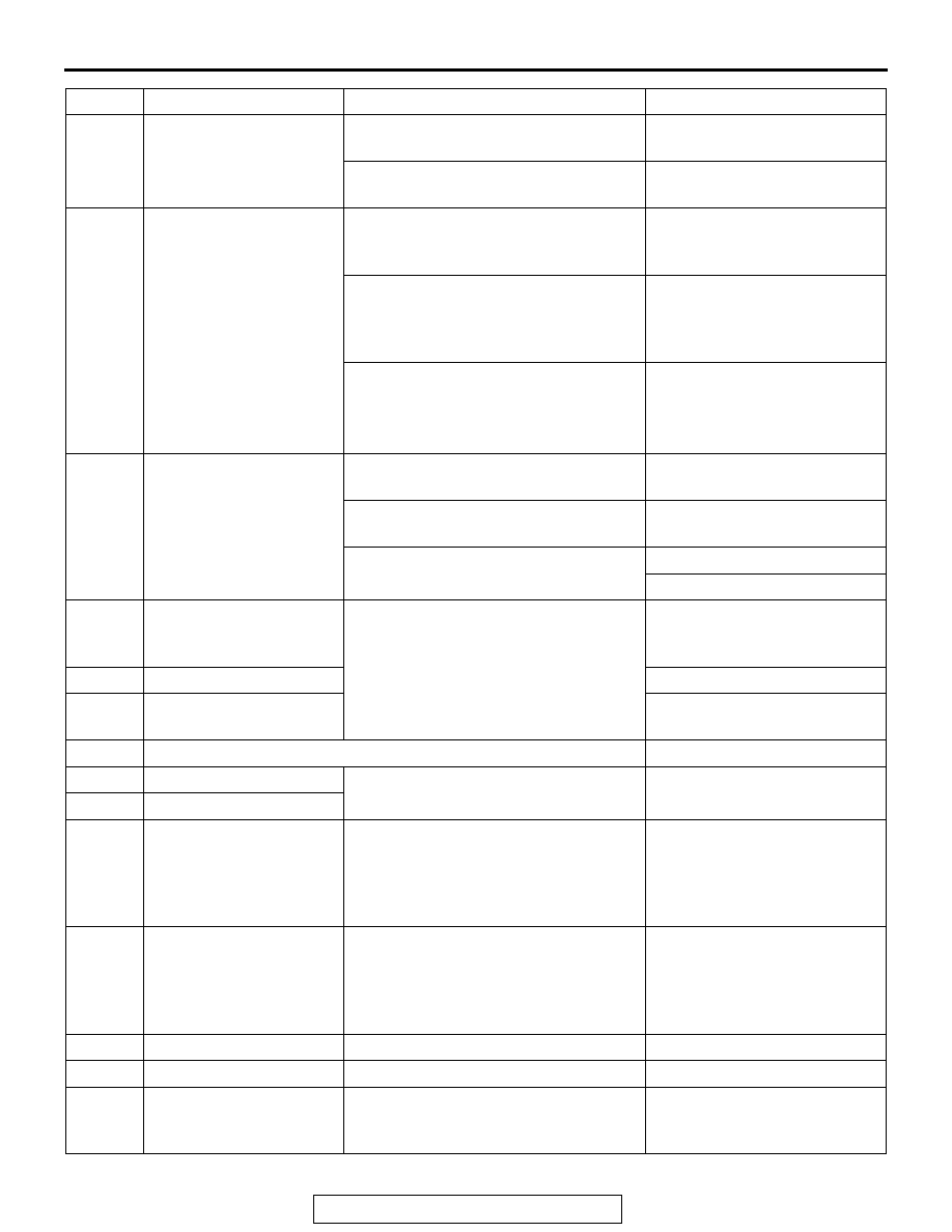
26
Brake fluid pressure
switch
Brake fluid level is lower than the
"LOWER" marking.
Low
Brake fluid level is higher than the
"LOWER" marking.
Normal
28
ASC/TCL off switch
When the ASC OFF switch is not
operated (when the ASC control is
available)
ON
When the ASC OFF switch is operated
(pressed and held for 3 seconds or
more)(when the ASC control is
prohibited)
OFF
When the ASC OFF switch is operated
(pressed and held for 15 seconds or
more)(when the ASC OFF control is
prohibited by fail-safe function)
*2
ON
45
SAS OK flag
When the steering wheel sensor
neutral point is learned
Comp
When the steering wheel sensor
neutral point is not learned
Not Comp
When the steering wheel sensor is
defective
SAS fail
SAS fail&No Comp
65
Engine Speed
When the accelerator pedal is
depressed (engine started)
The tachometer display and
the scan tool display almost
agree with each other.
66
Engine torque
Displays the engine torque.
67
APS
Displays the accelerator pedal
opening angle.
68
Allow ESP torque request
Permitted
70
Target gear
When the selector lever is operated
Displays the selector lever
position.
71
Actual gear
72
Master cylinder pressure
Offset
The difference between the neutral
position that was input to the
ASC-ECU before the master cylinder
pressure sensor calibration and the
neutral position after the calibration.
-8 to 8 bar
73
Lateral G sensor offset
The difference between the neutral
position that was input to the
ASC-ECU before the G and yaw rate
sensor calibration and the neutral
position after the calibration.
-0.15 to 0.15 G
86
Ignition switch
Ignition switch: ON
ON
87
Ignition switch (input)
Ignition switch: ON
ON
88
Vehicle speed
Perform a test run of the vehicle.
The speedometer display and
the scan tool display almost
agree with each other.
Item No. Check item
Check condition
Normal condition