Mitsubishi Outlander GS45X. Manual - part 1567


  Index      Mitsubishi     Mitsubishi Outlander GS45X - service repair manual


Search            


Content   ..  1565  1566  1567  1568   ..


Mitsubishi Outlander GS45X. Manual - part 1567


STEERING WHEEL

TSB Revision

POWER STEERING

37-31

STEERING WHEEL

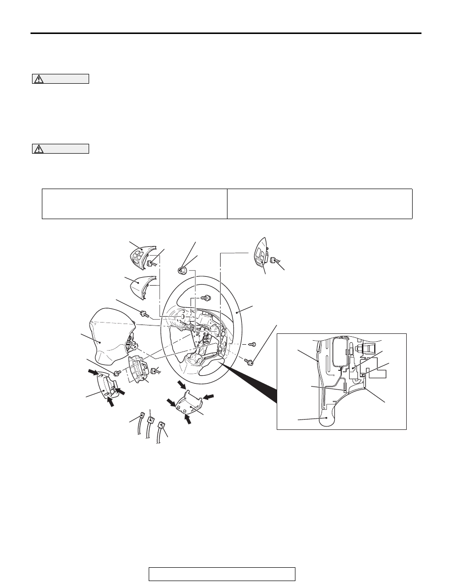
REMOVAL AND INSTALLATION

M1372011401692

WARNING

Before removing the steering wheel and driver’s air bag module assembly, refer to 
GROUP 52B, Service Precautions 

P.52B-25

 and Driver’s Air Bag Module and Clock Spring 

P.52B-439

.

When removing and installing the steering wheel, do not let it bump against the driver’s 
air bag module.

CAUTION

After the installation, perform a calibration for the ASC-ECU to learn the steering wheel sensor neutral 
point. (Refer to GROUP 35C 

 On-vehicle Service  Steering Wheel Sensor Calibration 

P.35C-283

). 

<Vehicles with ASC>

Pre-removal operation
Steering wheel straight-ahead position check

Post-installation operation
• Steering wheel straight-ahead position check

• Steering wheel shake check

AC611821

1

8

8

2

3

4

1

15

14

9.5 ± 2.5 N·m
84 ± 22 in-lb

44 ± 11 N·m
32 ± 8 ft-lb

Claw

Claw

AH

13

11

7

6

2.5 ± 0.5 N·m
22 ± 4 in-lb

Claw

Claw

15

4

3

2

10

Claw

Claw

Claw

9.5 ± 2.5 N·m
84 ± 22 in-lb

5

9

12

Removal steps 

<<

A

>>

1.

Cover

>>

B

<<

2.

Horn connector connection

>>

B

<<

3.

Steering switch connector 
connection

<<

B

>>

>>

B

<<

4.

Driver's air bag module connector 
connection

5.

Steering wheel voice control 
switch connector connection 
<Vehicles with steering wheel 
voice control switch>

6.

Steering wheel voice control 
switch cover <Vehicles with 
steering wheel voice control 
switch>

7.

Steering wheel voice control 
switch <Vehicles with steering 
wheel voice control switch>

<<

C

>>

>>

A

<<

8.

Driver's air bag module

9.

Cruise control switch connector 
connection

Removal steps (Continued)

STEERING WHEEL

TSB Revision

POWER STEERING

37-32

Required Special Tools:

• MB990784: Ornament Remover

• MB990803: Steering wheel puller

REMOVAL SERVICE POINTS

.

<<A>> COVER REMOVAL

Insert the ornament remover (Special tool: MB990784) into the 
notch shown in the figure, and remove the cover.

.

<<B>> DRIVER’S AIR BAG MODULE 
CONNECTOR REMOVAL

Slide the outer housing of the driver’s air bag module connector 
in the arrow direction shown, and disconnect the connector.

.

10. Cruise control switch
11. Bezel cover (LH) <Vehicles 

without steering wheel audio 
remote control switch>

12. Steering wheel audio remote 

control switch connector 
connection <Vehicles with 
steering wheel audio remote 
control switch>

Removal steps (Continued)

13. Steering wheel audio remote 

control switch <Vehicles with 
steering wheel audio remote 
control switch>

14. Flange nut

<<

D

>>

>>

A

<<

15. Steering wheel assembly

Removal steps (Continued)

AC505865AB

MB990784

Cover

AC607302

AC600868

Outer housing of the driver's air bag 
module connector

Horn connector

Lower column 
cover

Driver's air bag 
module connector 
(4-pin, yellow)

AB

STEERING WHEEL

TSB Revision

POWER STEERING

37-33

<<C>> DRIVER’S AIR BAG MODULE ASSEMBLY 
REMOVAL

WARNING

The air bag module must not be measured with 
such equipment as an ohmmeter.

The air bag module must not be disassembled.

The removed air bag module should be stored in a 
clean, dry place with the deployment surface fac-
ing up.

1. Using t-type long torx wrench (T30), a torx screw is loos-

ened completely and removed.

.

<<D>> STEERING WHEEL ASSEMBLY REMOVAL

1. Position the steering wheel in a straight ahead direction.

CAUTION

Use the special tool to remove the steering wheel since the 
steering column collision absorbing mechanism may be 
damaged.
Use special tool MB990803 to remove the steering wheel.

AC608854

AC609541AB

Equal to or more than

40mm (1.6 inch).

AC607307

MB990803

AB

STEERING WHEEL

TSB Revision

POWER STEERING

37-34

INSTALLATION SERVICE POINTS

.

>>A<< STEERING WHEEL ASSEMBLY/DRIVER'S 
AIR BAG MODULE INSTALLATION

After centering the clock spring (Refer to GROUP 52B - Air Bag 
Module Clock Spring 

P.52B-439

), install the steering wheel 

assembly.

.

>>B<< DRIVER’S AIR BAG MODULE 
CONNECTOR CONNECTION/STEERING SWITCH 
CONNECTOR CONNECTION/HORN CONNECTOR 
CONNECTION

Connect the connector securely and route the harnesses not to 
lie off the cover hole.


Content   ..  1565  1566  1567  1568   ..