Mitsubishi Outlander GS45X. Manual - part 1565


  Index      Mitsubishi     Mitsubishi Outlander GS45X - service repair manual


Search            


Content   ..  1563  1564  1565  1566   ..


Mitsubishi Outlander GS45X. Manual - part 1565


ON-VEHICLE SERVICE

TSB Revision

POWER STEERING

37-23

4. Move the ball joint stud several times and install the nut on 

the stud. Using the special tool ball joint removal MB990326, 
measure the ball joint breakaway torque.

Standard value: 2.9 N

m (26 in-lb) or less

5. If the rotation torque exceeds the standard value, replace 

the tie rod end. (Refer to 

P.37-45

).

6. If the rotation torque is under the standard value, check the 

ball joint for end play or ratcheting. If no end play or 
ratcheting, the ball joint can be re-used.

7. Install the tie rod end to the knuckle, then tighten a new 

self-locking nut to the specified torque.

Tightening torque: 25 

± 5 Nm (18 ± 3 ft-lb)

STATIONARY STEERING EFFORT CHECK

M1372001701001

1. Park the vehicle on a level paved road, position the steering 

wheel in the straight ahead direction.

2. Start the engine, and maintain the engine speed at 650 

± 

100 r/min <2.4L>, 600 

± 100 r/min <3.0L>.

3. Position the spring scale on the circumference of the 

steering wheel, and measure the steering force at the time 
when the steering wheel is turned to right or left side (within 
the range of one and a half turns) from the center position.


 At the same time, verify that the steering force does not 
vary excessively in both directions.

Standard value:

4. If not within the standard value, check and adjust the 

suspected components.

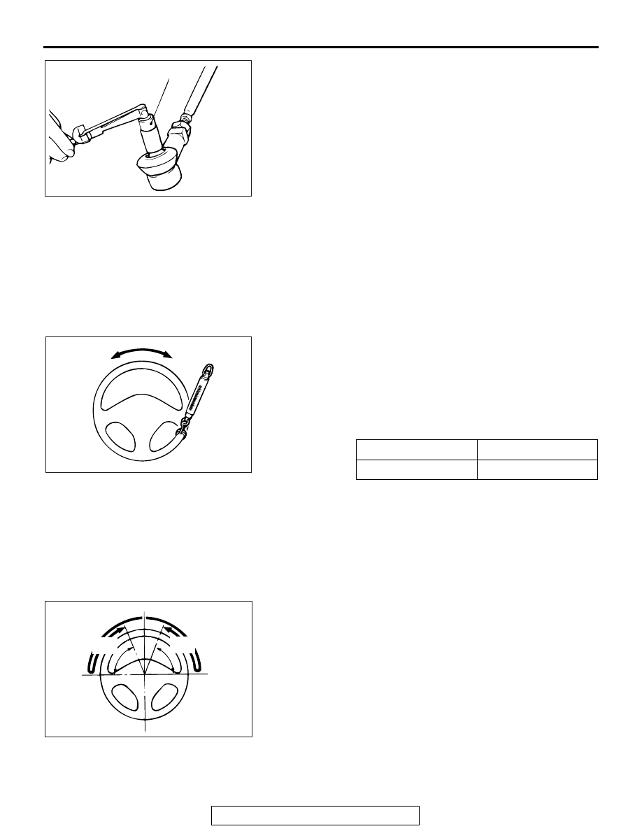
STEERING WHEEL RETURN TO CENTER CHECK

M1372001800801

Conduct a road test:
1. Make both gradual and sudden turns and check the steering 

wheel return. 

2. At a vehicle speed of approximately 22 mph (35 km/h), turn 

the steering wheel 90 degrees, hold a few seconds, then 
release. If the steering wheel then returns 70 degrees or 
more, the return can be judged satisfactory.
NOTE: There will be a momentary feeling or "heaviness" 
when the wheel is turned quickly, but this is not abnormal. 
(Oil pump discharge amount is especially apt to be insuffi-
cient during idling.) 

ACX01129 AB

MB990326

Steering force

29 (6.5 lb) N or less

Fluctuation band

5.9 (1.33 lb) N or less

AC000987

AC000989AC

70˚ or
more

70˚ or
more

ON-VEHICLE SERVICE

TSB Revision

POWER STEERING

37-24

DRIVE BELT TENSION CHECK

M1372001901072

Refer to GROUP 11A 

− On-vehicle service − Drive belt tension 

check 

P.11A-9

 <2.4L>, Refer to GROUP 11C 

− On-vehicle ser-

vice 

− Generator drive belt tension check 

P.11C-8

 <3.0L>.

FLUID LEVEL CHECK

M1372002000734

1. Park the vehicle on a flat, level surface.
2. Start the engine, and then turn the steering wheel several 

times to raise the temperature of the fluid to approximately 
50 

− 60°C (122 − 140°F).

3. With the engine running, turn the wheel all the way to the left 

and right several times.

4. Check the fluid in the oil reservoir for foaming or milkiness. 

Check the difference of the fluid level when the engine is 
stopped, and while it is running. If the change of the fluid 
level is 5 mm (0.2 inch) or more, air bleeding should be 
done.

FLUID REPLACEMENT

M1372002101187

.

<2.4L ENGINE>

1. Raise and support the front wheels.
2. Disconnect the return hose connection, and then connect a 

vinyl hose to the return hose, and drain the fluid into a 
container.

3. Disconnect the all of the injector connectors.
4. While operating the starter motor intermittently, turn the 

steering wheel all the way to the left and right several times 
to drain all of the fluid.

5. Connect the return hose securely, and then secure with the 

clip.

6. Fill the oil reservoir with GENUINE MITSUBISHI POWER 

STEERING FLUID or ATF DEXRON III/DEXRON II up to the 
lower position of the filler, and then bleed the air (Refer to 

P.37-25

).

.

AC608306

With engine stopped

AC

Fluid level change: Within 5 mm (0.2 in)

With engine running

AC703614

Return hose

AC

Container

AC705402 AC

Injector 
connectors

ON-VEHICLE SERVICE

TSB Revision

POWER STEERING

37-25

<3.0L ENGINE>

1. Raise and support the front wheels.
2. Disconnect the return hose connection, and then connect a 

vinyl hose to the return hose, and drain the fluid into a 
container.

3. Disconnect the camshaft position sensor connector.
4. While operating the starter motor intermittently, turn the 

steering wheel all the way to the left and right several times 
to drain all of the fluid.

5. Connect the return hose securely, and then secure with the 

clip.

6. Fill the oil reservoir with GENUINE MITSUBISHI POWER 

STEERING FLUID or ATF DEXRON III/DEXRON II up to the 
lower position of the filler, and then bleed the air (Refer to 

P.37-25

).

POWER STEERING SYSTEM AIR BLEEDING

M1372002201430

Perform air bleeding procedure as necessary after replacing 
the steering gear or the steering fluid lines.

.

<2.4L ENGINE>

Required Special Tools:

• MB991958: M.U.T.-III Sub Assembly

1. Raise and support the front wheels.
2. Disconnect the all of the injector connectors.

CAUTION

Perform air bleeding only while cranking the engine. If air 
bleeding is performed while the engine is running, air 
could enter the fluid. During air bleeding, refill the steering 
fluid supply so that the level never falls below the lower 
mark on the dipstick.
3. Turn the steering wheel all the way to the left and right five 

or six times while using the starter motor to crank the engine 
intermittently several times (for 15 to 20 seconds).

4. Connect the all of the injector connectors.
5. Start the engine (idling).
6. Turn the steering wheel to the left and right until there are no 

air bubbles in the oil reservoir.

7. Confirm that the fluid is not milky, and that the level is 

between the high and low dipstick marks.

8. Confirm that there is very little change in the fluid level when 

the steering wheel is turned left and right.

AC703614

Return hose

AC

Container

AC705403 AC

Camshaft position
sensor connector

AC705402 AC

Injector 
connectors

ON-VEHICLE SERVICE

TSB Revision

POWER STEERING

37-26

CAUTION

If the fluid level rises suddenly after the engine is stopped, 
the air has not been completely bled. If air bleeding is not 
complete, there will be abnormal noises from the pump 
and the flow-control valve, and this condition could cause 
reduce the life of the power steering components.
9. Confirm that the change in the fluid level is no more than 5 

mm (0.2 inch) when the engine is stopped and when it is 
running.

10.If the change of the fluid level is 5 mm (0.2 inch) or more, 

the air has not been completely bled from the system. The 
air bleeding procedure must be repeated.

11.Use scan tool to check if the diagnostic trouble code is set. If 

the diagnostic trouble code is set, erase it.

.

<3.0L ENGINE>

Required Special Tools:

• MB991958: M.U.T.-III Sub Assembly

1. Raise and support the front wheels.
2. Disconnect the camshaft position sensor connector.

CAUTION

Perform air bleeding only while cranking the engine. If air 
bleeding is performed while the engine is running, air 
could enter the fluid. During air bleeding, refill the steering 
fluid supply so that the level never falls below the lower 
mark on the dipstick.
3. Turn the steering wheel all the way to the left and right five 

or six times while using the starter motor to crank the engine 
intermittently several times (for 15 to 20 seconds).

AC608306

With engine stopped

AC

Fluid level change: Within 5 mm (0.2 in)

With engine running

AC505420 AF

M.U.T.-III main harness A

V. C. I.

USB cable

Diagnosis connector

AC705403 AC

Camshaft position
sensor connector


Content   ..  1563  1564  1565  1566   ..