Mitsubishi Outlander GS45X. Manual - part 1566


  Index      Mitsubishi     Mitsubishi Outlander GS45X - service repair manual


Search            


Content   ..  1564  1565  1566  1567   ..


Mitsubishi Outlander GS45X. Manual - part 1566


ON-VEHICLE SERVICE

TSB Revision

POWER STEERING

37-27

4. Connect the all of the injector connectors.
5. Start the engine (idling).
6. Turn the steering wheel to the left and right until there are no 

air bubbles in the oil reservoir.

7. Confirm that the fluid is not milky, and that the level is 

between the high and low dipstick marks.

8. Confirm that there is very little change in the fluid level when 

the steering wheel is turned left and right.

CAUTION

If the fluid level rises suddenly after the engine is stopped, 
the air has not been completely bled. If air bleeding is not 
complete, there will be abnormal noises from the pump 
and the flow-control valve, and this condition could cause 
reduce the life of the power steering components.
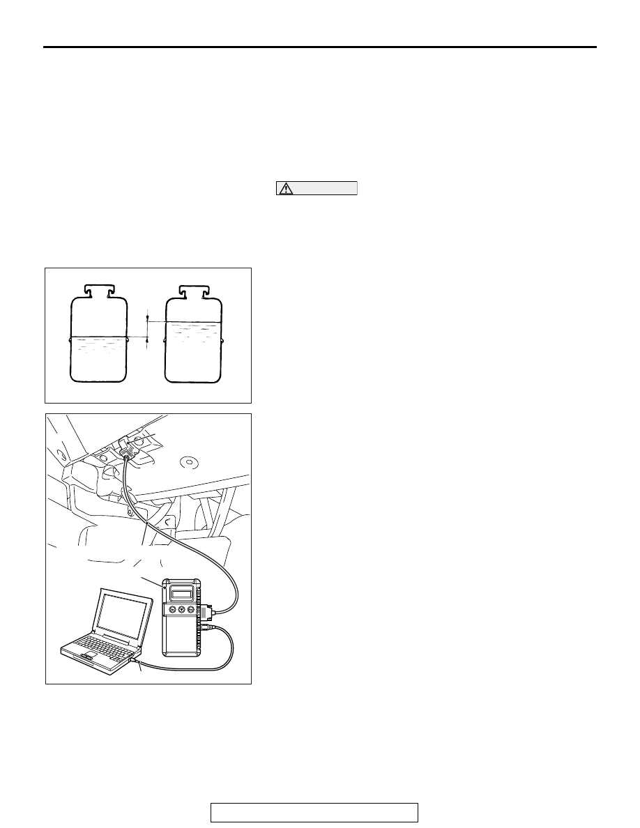
9. Confirm that the change in the fluid level is no more than 5 

mm (0.2 inch) when the engine is stopped and when it is 
running.

10.If the change of the fluid level is 5 mm (0.2 inch) or more, 

the air has not been completely bled from the system. The 
air bleeding procedure must be repeated.

11.Use scan tool to check if the diagnostic trouble code is set. If 

the diagnostic trouble code is set, erase it.

AC608306

With engine stopped

AC

Fluid level change: Within 5 mm (0.2 in)

With engine running

AC505420 AF

M.U.T.-III main harness A

V. C. I.

USB cable

Diagnosis connector

ON-VEHICLE SERVICE

TSB Revision

POWER STEERING

37-28

OIL PUMP PRESSURE TEST

M1372002301073

Required Special Tools:

• MB990662: Power Steering Oil Pressure Gauge

• MB991548: Oil Pressure Gauge Adapter A (Pump Side)

• MB991549: Oil Pressure Gauge Adapter B (Hose Side)

1. Disconnect the pressure hose from the oil pump, and then 

connect special tools MB991548, MB990662 and 
MB991549.

2. Bleed air, then turn the steering wheel several times while 

the vehicle is not moving so that the temperature of the fluid 
rises to approximately 50 

− 60°C (122 − 140°F).

3. Start the engine and idle it at 650 

± 100 r/min <2.4L>, 600 ± 

100 r/min <3.0L>.

CAUTION

The pressure gauge shut-off valve must not remain closed 
for more than 10 seconds.
4. Fully close the shut-off valve of the pressure gauge and 

measure the oil pump relief pressure to confirm that it is 
within the standard value range. Open it again immediately 
after checking the pressure.

Standard value: 8.8 

 9.5 MPa (1,276  1,378 psi)

5. If it is not within the standard value, replace the oil pump.
6. Check whether or not the hydraulic pressure is the standard 

value when no-load conditions are created by fully opening 
the shut-off valve of the pressure gauge.

Standard value: 0.2 

 0.7 MPa (29  102 psi)

7. If it is not within the standard value, the probable cause is a 

malfunction of the oil line or steering gear, so check these 
parts and repair as necessary.

8. Turn the steering wheel all the way to the left or right; then 

check whether or not the retention hydraulic pressure is the 
standard value.

Standard value: 8.8 

 9.5 MPa (1,276  1,378 psi)

9. If not the standard value, overhaul the steering gear. 

Remeasure fluid pressure.

10. Remove the special tools power steering oil pressure 

gauge adapter MB991548, MB990662 and MB991549, and 
then tighten the pressure hose to the specified torque.

Tightening torque: 57 

± 7 Nm (42 ± 5 ft-lb)

11. Bleed the system (Refer to 

P.37-25

).

AC609397AC

Temperature

Oil reservoir

Power steering oil 
pressure gauge
(MB990662)

Shut-off valve

Oil
pump

Oil pressure 
gaige adapter B
(MB991549)

Oil pressure 
gauge 
adapter A
(MB991548)

ON-VEHICLE SERVICE

TSB Revision

POWER STEERING

37-29

POWER STEERING PRESSURE SWITCH CHECK

M1372007200788

Required Special Tools:

• Oil pressure gauge adapter A (pump side) (MB991548)

• Oil pressure gauge adapter B (hose side) (MB991549)

• Power steering oil pressure gauge (MB990662)

1. Disconnect the pressure hose from the oil pump, and then 

connect special tools MB991548, MB990662 and 
MB991549.

2. Bleed air, and then turn the steering wheel several times 

while the vehicle is not moving so that the temperature of 
the fluid rises to approximately 50 

− 60°C (122 − 140°F).

3. The engine should be idling.
4. Disconnect the connector for the oil pressure switch, and 

place an ohmmeter at the switch.

5. Gradually close the shut-off valve of the pressure gauge and 

increase the hydraulic pressure, then check whether or not 
the hydraulic pressure that activates the switch is the 
standard value.

Standard value: 1.5 

 2.0 MPa (218  290 psi)

6. Gradually open the shut-off valve and reduce the hydraulic 

pressure; then check whether or not the hydraulic pressure 
that deactivates the switch is the standard value.

Standard value: 0.5 

 2.0 MPa (73  290 psi)

7. Remove the special tools, and then tighten the pressure 

hose to the specified torque.

Tightening torque: 57 

± 7 Nm (42 ± 5 ft-lb)

8. Bleed the system (Refer to 

P.37-25

).

INSPECTION OF STEERING COLUMN SHAFT 
ASSEMBLY IMPACT ABSORBING MECHANISM

M1372013500658

If a collision accident occurs or severe impact is applied on the 
steering wheel, the collision energy absorbing mechanism may 
have operated. Once the mechanism has operated, it will be 
inoperative even it has suffered no apparent damage. Deter-
mine if the steering column shaft can be reused by the following 
procedure. If the collision energy absorbing mechanism has 
already operated, replace the steering column shaft assembly.
If any excessive radial free play on the steering wheel is found 
with the tilt lever in the lock position, always replace the steer-
ing shaft assembly.

AC604168 AC


Shut-off 
valve

Temperature 
gauge

Oil 
pump

Oil reservoir

Power steering 
oil pressure gauge
(MB990662)

Oil pressure 
gauge adapter A
(MB991548)

Oil pressure 
gauge adapter B
(MB991549)

ON-VEHICLE SERVICE

TSB Revision

POWER STEERING

37-30

WARNING

If the vehicle continues to be driven after the colli-
sion absorbing mechanism has operated, the 
steering column shaft may be damaged while it is 
in use.

If there is a slack in the one-way capsule, do not 
attempt to repair it but replace the steering column 
shaft assembly.

INSPECTION PROCEDURE

1. Remove the ignition key cover, steering column lower cover, 

steering column upper cover, WCM, bottom cover assembly 
(driver's seat), side air outlet (L) and side lower panel 
assembly.

CAUTION

After inspection, do not release the tilt lever until the steer-
ing shaft assembly has been installed.
2. Ensure that the tilt lever is in the lock position.
3. Loosen the two upper steering column mounting bolts by 

two turns.

4. Hold the one-way capsules as shown in the figure, and then 

try to rock them. If there is a slack in either of the capsules, 
replace the steering column shaft assembly.

CAUTION

• Be careful that nothing is pinched between the one-way 

capsules and the body.

• When the replacement, removal, or installation of the 

steering column shaft assembly is performed, tighten 
the mounting bolt of the one-way capsule side to the 
specified torque first.

5. If no malfunction has been found after the inspection, 

hand-tighten the steering column mounting bolts, and then 
tighten them to the specified torque.

Tightening torque: 12 

± 3 Nm (106 ± 26 in-lb)

AC703615AB


Steering column
mounting bolt

Tilt lever

Steering 
column 
assembly

One-way capsule

AC703616AB

One-way capsule


Content   ..  1564  1565  1566  1567   ..