Mitsubishi Outlander GS45X. Manual - part 1564


  Index      Mitsubishi     Mitsubishi Outlander GS45X - service repair manual


Search            


Content   ..  1562  1563  1564  1565   ..


Mitsubishi Outlander GS45X. Manual - part 1564


ON-VEHICLE SERVICE

TSB Revision

POWER STEERING

37-19

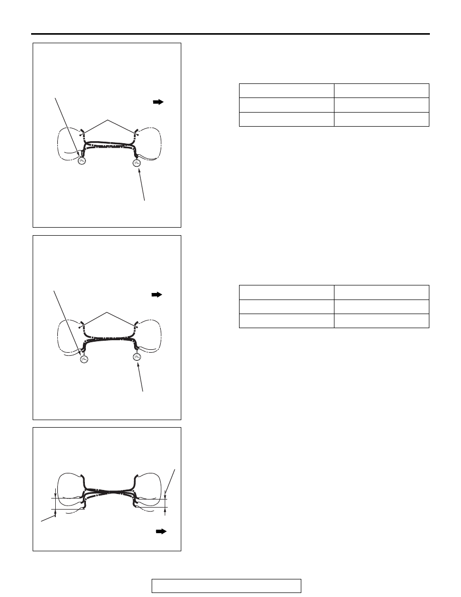
(1)  While pushing the "Position B" with the specified load by 

wheel size, read the values on the dial gauges at the " 
Position a" and "Position b". The values of the dial 
gauges at this time shall respectively be "aB" and "bB".

(2) Remove the load in the "Position B". Then while pushing 

the "Position A" with the specified load by wheel size, 
read the values on the dial gauge in the "Position a" and 
"Position b". The values on the dial gauges at this time 
shall respectively be "aA" and "bA".

(3) Make calculation taking the value differences of the dial 

gauge positions a and b which were read while pushing 
the "Position A" and "Position B" as each fluctuation.

• Fluctuation of the dial gauge position a: aA − aB

• Fluctuation of the dial gauge position b: bA − bB

(4) Calculate each fluctuation difference of the dial gauge 

positions a and b acquired above for looseness. Perform 
the procedure above twice.
Fluctuation of the dial gauge position a 

− Fluctuation of 

the dial gauge position b

(5) Calculate the average of the looseness calculated twice.

Wheel size

Specified load

16 inches

120 N

18 inches

100 N

Wheel size

Specified load

16 inches

120 N

18 inches

100 N

AC901382

Value of the dial gauge position a

Value of the dial gauge 
position b

Status before measurement

Reading the value on the dial gauge 
with the Position B pushed

AB

Vehicle front

AC901681

Status with the Position B 
pushed

AB

Reading the value on the dial gauge 
with the Position A pushed

Value of the dial gauge 
position b

Vehicle front

Value of the dial gauge position a

AC901381

Fluctuation of the dial gauge 
position b with the Position A 
and Position B pushed

Fluctuation of the dial gauge 
position a with the Position A 
and Position B pushed

Fluctuation of the value on the 
dial gauge

AB

Vehicle front

ON-VEHICLE SERVICE

TSB Revision

POWER STEERING

37-20

6. If the average exceeds the standard value, check the tie rod 

end ball joint rotation torque. (Refer to 

P.37-22

.)

Standard value: Within 

± 2.0 mm (0.08 in)

NOTE: Measure the tie-rod looseness on the right side and 
left side respectively.

When a spring scale is used

1. Carry out the confirmation before the looseness check with 

the same manner as the check using a push-pull gauge.

2. At the position that is 25 mm (1.0 in) above from the wheel 

centre, bind the tyre and the wheel rim with a cord for both 
the front and rear sides, and fix them with a tape not to loose 
vertically.

3. Set the spring scale to the cord bound as above. At this 

time, the point to pull shall be in the dimension between the 
"Position C" and "Position D" by wheel size, and the position 
on the vehicle front side shall be the "Position C" and the 
vehicle rear side shall be the "Position D".

4. To stabilize the relationship between the load and 

fluctuation, pull with the specified load by wheel size in the 
order of "Position C", "Position D", and "Position C" using 
the spring scale. Note that the pulled load on each position 
shall be extracted.

5. Using the spring scale, carry out the procedure below to 

read the value on the dial gauge and calculate the 
looseness.
NOTE: The +/

 sign acquired with the calculation result shall 

be used as it is.

Wheel size

− D dimension

16 inches

500 

− 525 mm (19.7 − 

20.7 in)

18 inches

555 mm (21.9 in)

Wheel size

Specified load

16 inch steel wheel

120 N

16 inch aluminum wheel 100 N

18 inch

80 N

AC808017

AB

D

C

Front of vehicle

Tape

AC808584

AB

25 mm
(1.0 in)

AB

Dimension between 
Positions C and D

Position C

Position D

Vehicle front

Wheel center

Point of load

AC901691

AB

Spring scale

Position D

Point of load for spring scale

Vehicle front

Position C

ON-VEHICLE SERVICE

TSB Revision

POWER STEERING

37-21

(1)  While pulling the "Position D" with the specified load by 

wheel size, read the values on the dial gauges in the 
"Position a" and "Position b". The values on the dial 
gauges at this time shall respectively be "aD" and "bD".

(2)  Remove the load at the "Position D". Then while pulling 

the "Position C" with the specified load by wheel size, 
read the values on the dial gauge in the "Position a" and 
"Position b". The values on the dial gauges at this time 
shall respectively be "aC" and "bC".

(3) Make calculation taking the value differences of the dial 

gauge positions a and b which were read while pulling 
the "Position C" and "Position D" as each fluctuation.

• Fluctuation of the dial gauge position a: aC − aD

• Fluctuation of the dial gauge position b: bC − bD

(4) Calculate each fluctuation difference of the dial gauge 

positions a and b acquired above for looseness. Perform 
the procedure above twice.
Fluctuation of the dial gauge position a 

− Fluctuation of 

the dial gauge position b

(5) Calculate the average of the looseness calculated twice.

Wheel size

Specified load

16 inch steel wheel

120 N

16 inch aluminum wheel 100 N

18 inch

80 N

Wheel size

Specified load

16 inch steel wheel

120 N

16 inch aluminum wheel 100 N

18 inch

80 N

AC901681

Reading the value on the dial gauge 
with the Position D pulled

AC

Point before measurement

Value of the dial gauge 
position b

Value of the dial gauge position a

Vehicle front

AC901382

Reading the value on the dial gauge 
with the Position C pulled

AC

Status with the Position C 
pulled

Value of the dial gauge position a

Value of the dial gauge position b

Vehicle front

AC901381

Fluctuation of the dial gauge 
position b with the Position C 
and Position D pulled

Fluctuation of the dial gauge position a 
with the Position C and Position D pulled

Fluctuation of the value 
on the dial gauge

AC

Vehicle front

ON-VEHICLE SERVICE

TSB Revision

POWER STEERING

37-22

6. If the average exceeds the standard value, check the tie rod 

end ball joint rotation torque. (Refer to 

P.37-22

.)

Standard value: Within 

± 2.0 mm (0.08 in)

NOTE: Measure the tie-rod looseness on the right side and 
left side respectively.

BALL JOINT DUST COVER CHECK

M1372008600756

1. Using your fingers, press the dust cover to check for cracks 

or damage.

2. If there are any cracks in the dust cover or it is damaged, 

replace the tie-rod end (Refer to 

P.37-45

).

NOTE: If the dust cover has a crack or damage, the ball 
joint could be damaged.

TIE ROD END BALL JOINT ROTATION TORQUE 
CHECK

M1372001500822

Required Special Tools:

• MB990326: Preload Socket

• MB991897 or MB992011: Ball Joint Remover

CAUTION

• Do not remove the nut from ball joint. Loosen it and use 

the special tool ball joint removal MB991897 or 
MB992011 to avoid possible damage to the ball joint 
threads.

• Hang the special tool ball joint removal MB991897 or 

MB992011 with cord to prevent it from falling. 

1. Install the special tool ball joint removal MB991897 or 

MB992011 as shown in the figure.

2. Turn the bolt and knob as necessary to make the jaws of the 

special tool ball joint removal MB991897 or MB992011 
parallel, tighten the bolt by hand and confirm that the jaws 
are still parallel.
NOTE: When adjusting the jaws in parallel, make sure the 
knob is in the position shown in the figure.

3. Tighten the bolt with a wrench to disconnect the tie rod end.

AC703613AB

Cord

Bolt

MB991897
or
MB992011

Nut

Ball joint

AC106821

Knob

Parallel

Bolt

Correct

Wrong

AH


Content   ..  1562  1563  1564  1565   ..