Mitsubishi Outlander GS45X. Manual - part 1548


  Index      Mitsubishi     Mitsubishi Outlander GS45X - service repair manual


Search            


Content   ..  1546  1547  1548  1549   ..


Mitsubishi Outlander GS45X. Manual - part 1548


ON-VEHICLE SERVICE

TSB Revision

BASIC BRAKE

35A-21

BRAKE PAD CHECK

M1351017300220

CAUTION

If there is a significant difference in thickness between the 
brake pads at right and left, check the sliding area and the 
runout of the brake disk (Refer to 

P.35A-24

).

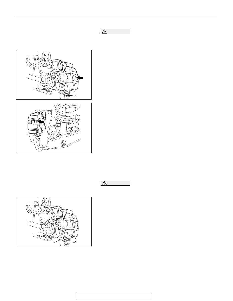
1. Visually check the thickness of brake pad from the 

inspection hole of the caliper body.

Standard value: 10.0 mm (0.39 inch)
Limit: 2.0 mm (0.08 inch)

2. If the brake pad thickness is less than the limit value, 

replace the brake pad (Refer to 

P.35A-21

).

BRAKE PAD REPLACEMENT

M1351017400294

.

<FRONT>

CAUTION

When replacing, replace both brake pads (right and left) as 
a set.
1. Remove the parts indicated in the figure, swivel the caliper 

body upward and retain it with a wire or similar tool.

AC505542 AB

<Front>

AC505543 AB

<Rear>

AC505542AH

<Front>

Guide pin

ON-VEHICLE SERVICE

TSB Revision

BASIC BRAKE

35A-22

2. Remove the following parts from the caliper body.

(1) Shim
(2) Brake pad assembly
(3) Clip

CAUTION

Keep grease or other soiling off the pad and brake disk 
friction surfaces.
3. Clean the piston part, and press the piston into the cylinder 

using the special tool piston expander (MB990520).

4. Assemble the shim, brake pad assembly and clip to the 

caliper support, and tighten the guide pin to the specified 
torque.

Tightening torque: 44 

± 5 Nm (32 ± 4 ft-lb)

NOTE: Install the brake pad assembly (with wear indicator) 
to the inner side of the brake disk, making sure that the wear 
indicator is located on the top.

.

AC803273

<Right side>

<Left side>

Vehicle out side

Vehicle out side

AB

3

3

3

1

3

1

Wear indicator

1

1

2

2

AC706162AB

MB990520

Piston

Caliper body

ON-VEHICLE SERVICE

TSB Revision

BASIC BRAKE

35A-23

LUBRICATION POINT

.

<REAR>

CAUTION

When replacing, replace both brake pads (right and left) as 
a set.
1. Remove the parts indicated in the figure, swivel the caliper 

body upward and retain it with a wire or similar tool.

2. Remove the following parts from the caliper body.

(1) Shim
(2) Brake pad assembly
(3) Clip

AC705514AF

Grease: Repair kit grease (Color: Translucent
              red), Niglube RX-2 or equivalent

AC505543AH

<Rear>

Guide pin

AC900716

<Right side>

<Left side>

AB

Wear indicator

2

3

3

1

3

2

3

1

1

1

Vehicle out side

Vehicle out side

ON-VEHICLE SERVICE

TSB Revision

BASIC BRAKE

35A-24

CAUTION

Keep grease or other soiling off the pad and brake disk 
friction surfaces.
3. Clean the piston part, and press the piston into the cylinder 

using the special tool piston expander (MB990520).

4. Assemble the shim, brake pad assembly and clip to the 

caliper support, and tighten the guide pin to the specified 
torque.

Tightening torque: 44 

± 5 Nm (32 ± 4 ft-lb)

NOTE: Install the brake pad assembly (with wear indicator) 
to the inner side of the brake disk, making sure that the wear 
indicator is located on the bottom.

.

LUBRICATION POINT

BRAKE DISC CHECK

M1351018600257

CAUTION

Disc brakes must be kept within the allowable 
service values in order to maintain normal brake 
operation.
Before turning the brake disc, the following condi-
tions should be checked.

AC706162AB

MB990520

Piston

Caliper body

AC802113AB

Grease: Niglube RM or equivalent

AC801367AB

Grease: Repair kit grease (Color: Yellow)


Content   ..  1546  1547  1548  1549   ..