Mitsubishi Outlander GS45X. Manual - part 1549


  Index      Mitsubishi     Mitsubishi Outlander GS45X - service repair manual


Search            


Content   ..  1547  1548  1549  1550   ..


Mitsubishi Outlander GS45X. Manual - part 1549


ON-VEHICLE SERVICE

TSB Revision

BASIC BRAKE

35A-25

.

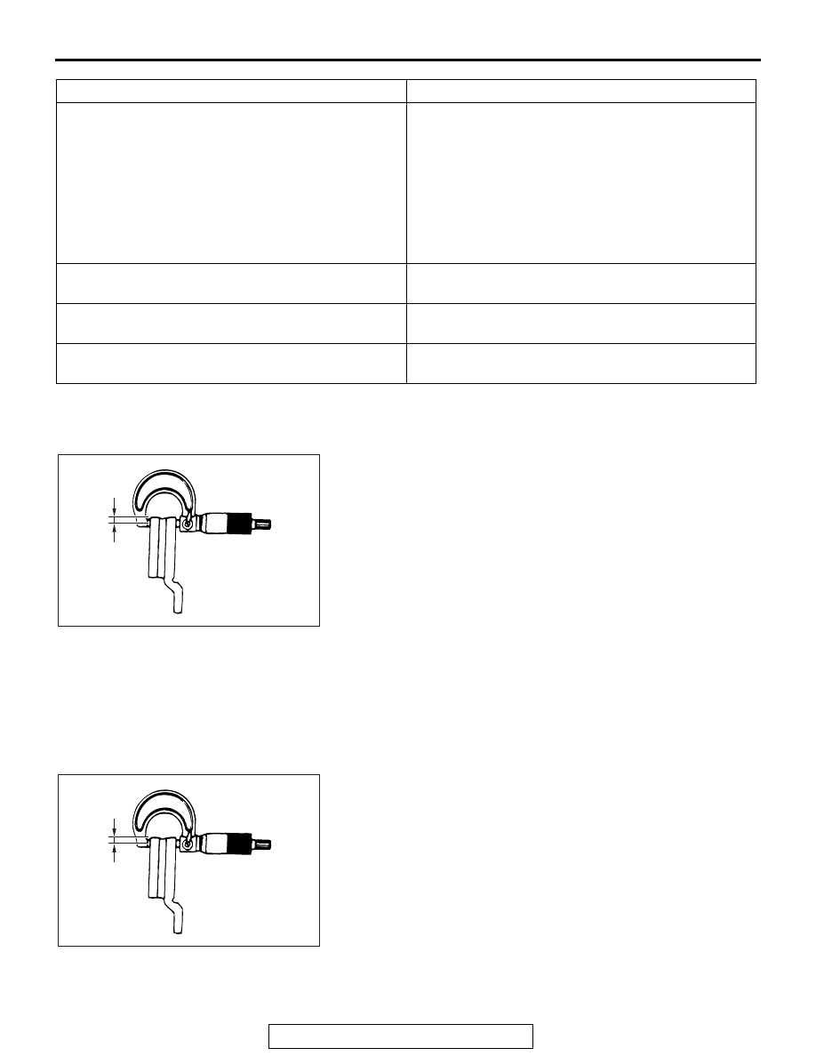
BRAKE DISC THICKNESS CHECK

1. Remove contaminants or corrosion from the brake disc 

surface.

2. Use a micrometer to measure the brake disc thickness at 

minimum eight points which are 10 mm (0.39 inch) inward 
from its circumference.

Standard value:

26.0 mm (1.02 inch) <Front>
10.0 mm (0.39 inch) <Rear>

Limit:

24.4 mm (0.96 inch) <Front>
8.4 mm (0.33 inch) <Rear>

3. If the brake disc thickness is worn beyond the limit value at 

more than one point, replace the brake disc and check its 
run-out.

.

BRAKE DISC THICKNESS UNEVENNESS CHECK 
AND CORRECTION

1. Remove contaminants or corrosion from the brake disc 

surface.

2. Use a micrometer to measure the brake disc thickness at 

minimum eight points which are 10 mm (0.39 inch) inward 
from its circumference. Then record the measurements.

3. If the brake disc thickness unevenness (the difference 

between the maximum and minimum values measured 
above) is 0.015 mm (0.0006 inch) or less, it is within the 
standard value.

4. If the brake disc thickness unevenness exceeds the 

standard value, grind it according to the procedure below 
while it is mounted on the vehicle.
NOTE: If it is suspected that the brake disc thickness will 
become less than the limit value after the grinding, replace 
the brake disc and check its run-out.

INSPECTION ITEM

REMARK

Scratches, rust, saturated lining materials and wear

• If the vehicle is not driven for a long period of 

time, sections of the discs that are not in contact 
with the pads will become rusty, causing noise 
and shuddering.

• If grooves and scratches resulting from excessive 

disc wear are not removed prior to installing a new 
pad assembly, there will be inadequate contact 
between the disc and the lining (pad) until the 
pads conform to the disc.

Run-out

Excessive run-out of the discs will increase the pedal 
depression resistance due to piston kick-back.

Change in thickness (parallelism)

If the thickness of the disc changes, this will cause 
pedal pulsation, shuddering and surging.

Inset or warping (flatness)

Overheating and improper handling while servicing 
will cause warping or distortion.

ACX00668AH

Approx. 10 mm
(0.39 inch)

ACX00668AH

Approx. 10 mm
(0.39 inch)

ON-VEHICLE SERVICE

TSB Revision

BASIC BRAKE

35A-26

(1) Check for wheel bearing looseness in the axial direction 

(Refer to GROUP 26 

− On-vehicle Service, Wheel 

bearing end play check 

P.26-11

 <Front>, GROUP 27A 

− 

On-vehicle Service, Wheel bearing end play check 

P.27A-6

 <Rear (FWD)> or GROUP 27B 

− On-vehicle 

Service, Wheel bearing end play check 

P.27B-17

 <Rear 

(AWD)>).

CAUTION

• Insert M12 plain washer and then install the adapter as 

shown before grinding.Failure to use the M12 plain 
washer will cause the brake disc to be deformed and 
ground incorrectly.

• To grind the brake disc, ensure that all the nuts (M12 X 

1.5) are tightened evenly and in a diagonal sequence to 
the specified torque [100 N

m (74 ft-lb)].Failure to use 

all the nuts (M12

×1.5), excessive or uneven tightening 

torque will cause the brake disc to deform or judder.

(2) Correct the brake disc uneven thickness by grinding it 

while in place on the vehicle.

.

BRAKE DISC RUN-OUT CHECK AND 
CORRECTION

1. Check for wheel bearing looseness in the axial direction 

(Refer to GROUP 26 

− On-vehicle Service, Wheel bearing 

end play check 

P.26-11

 <Front>, GROUP 27A 

− On-vehicle 

Service, Wheel bearing end play check 

P.27A-6

 <Rear 

(FWD)> or GROUP 27B 

− On-vehicle Service, Wheel 

bearing end play check 

P.27B-17

 <Rear (AWD)>).

2. If the end play is within the limit value, secure the brake disc 

by tightening the nut (M12

×1.5) evenly to the specified 

torque [100 N

⋅m (74 ft-lb)].If the end play still exceeds the 

limit value, replace the wheel bearing. Then secure the 
brake disc by tightening the nut (M12

×1.5) evenly to the 

specified torque [100 N

⋅m (74 ft-lb)].

3. Place a dial gauge ca. 5 mm (0.2 inch) inward from the 

circumference of the brake disc to measure its run-out.

Limit:

0.06 mm (0.0024 inch) <Front>
0.08 mm (0.0032 inch) <Rear>

4. If the brake disc run-out exceeds the limit value, rephase the 

brake disc to the hub so that the minimum brake disc run-out 
is obtained.

AC006226 AE

M12 Flat washer

M12 Flat washer

ACX00669AG

Approx. 5 mm (0.2 inch)

ON-VEHICLE SERVICE

TSB Revision

BASIC BRAKE

35A-27

CAUTION

• Insert M12 plain washer and then install the adapter as 

shown before grinding.Failure to use the M12 plain 
washer will cause the brake disc to be deformed and 
ground incorrectly.

• To grind the brake disc, ensure that all the nuts (M12 X 

1.5) are tightened evenly and in a diagonal sequence to 
the specified torque [100 N

m (74 ft-lb)].Failure to use 

all the nuts (M12

×1.5), excessive or uneven tightening 

torque will cause the brake disc to deform or judder.

5. If the brake disc run-out exceeds the limit value after 

rephasing, grind the disc while in place on the vehicle so 
that the brake disc run-out is within the limit value.
NOTE: If it is suspected that the brake disc thickness will be 
below the limit value, replace the brake disc.Then rephase 
the brake disc so that the minimum brake disc run-out is 
obtained, or grind the disc while in place on the vehicle so 
that its run-out is below the limit value.

BRAKE DRAG FORCE CHECK

M1351017200245

1. Remove the brake pad, shim and clip (Refer to 

P.35A-21

).

2. Using a spring scale, measure the hub sliding torque in the 

forward direction with the brake pad, shim and clip removed.

3. Install the brake pad, shim and clip (Refer to 

P.35A-21

).

4. Start the engine, and depress the brake pedal lightly two or 

three times. Then stop the engine. [Depressing force: 
approximately 50 

− 100 N (11.2 − 22.5 pound)]

5. Turn the brake disk 10 times in the forward direction.
6. Using a spring scale, measure the hub sliding torque in the 

forward direction with the brake pad, shim and clip installed.

7. Obtain the disk brake drag force (difference between 

measured values of item 2 and item 6).

Standard value: 68 N (15.3 pounds) or less

8. If the brake drag force exceeds the standard value, 

disassemble the brake caliper assembly to check for 
fouling/rust on the piston sliding section and piston seal 
deterioration, and confirm whether the guide pin and lock pin 
slide properly (Refer to 

P.35A-35

 <Front> or 

P.35A-41


<Rear>).

AC006226 AE

M12 Flat washer

M12 Flat washer

AC707502AB

Front of vehicle

BRAKE PEDAL

TSB Revision

BASIC BRAKE

35A-28

BRAKE PEDAL

REMOVAL AND INSTALLATION

M1351003401432

CAUTION

Do not apply grease or lubricant to the switch and the switch installation section to avoid malfunction 
of the switch. In addition, do not use gloves which have grease on them.

REMOVAL SERVICE POINT

.

<<A>> BRAKE PEDAL ASSEMBLY REMOVAL

From the engine compartment side, remove the brake pedal 
assembly while pulling the brake booster.

AC900819

6

4

5

3

2

8

7

9

1

10

AB

14 ± 3 N·m
11 ± 2 ft-lb

15 ± 3 N·m
11 ± 2 ft-lb

Removal steps 

1.

Stoplight relay connector 
connection

2.

Stoplight relay

3.

Stoplight switch connector 
connection

4.

Stoplight switch

5.

Pedal clip

6.

Pedal stopper

7.

Snap pin

8.

Pin assembly

9.

Pedal pad

<<

A

>>

10. Brake pedal assembly

Removal steps (Continued)


Content   ..  1547  1548  1549  1550   ..