Content .. 1536 1537 1538 1539 ..
Mitsubishi Outlander GS45X. Manual - part 1538
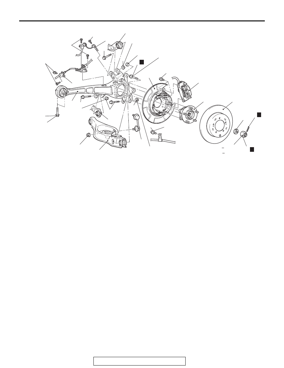
TRAILING ARM ASSEMBLY
TSB Revision
REAR SUSPENSION
34-21
Required Special Tool:
• MB990767: Front Hub and Flange Yoke Holder
AC802599
110 ± 11 N·m
81 ± 8 ft-lb
8.5 ± 1.5 N·m
76 ± 13 in-lb
11 ± 2 N·m
98 ± 17 in-lb
11 ± 2 N·m
98 ± 17 in-lb
71 ± 10 N·m
52 ± 7 ft-lb
39 ± 6 N·m
29 ± 4 ft-lb
90 ± 9 N·m
67 ± 6 ft-lb
N
<AWD>
144 176 N·m
107 129 ft-lb
*1
*1
*2
*2
*1
*2
*2
*2
*1
*1
*1
AC
95 ± 14 N·m
70 ± 10 ft-lb
N
58 ± 7 N·m
43 ± 5 ft-lb
*3
*2
71 ± 10 N·m
52 ± 7 ft-lb
*1
*1
145 ± 15 N·m
107 ± 11 ft-lb
11 ± 2 N·m
98 ± 17 in-lb
9
10
11
12
13
14
16
15
1
2
3
4
5
6
7
8
N
*3
Removal steps
1.
Cotter pin
<<
A
>> >>
B
<< 2.
Driveshaft nut
>>
B
<< 3.
Washer
4.
Rear wheel speed sensor
5.
Brake hose bracket
<<
B
>>
6.
Caliper assembly
7.
Brake disk
•
Driveshaft (Refer to Driveshaft
Removal and Installation
.)
8.
Rear wheel hub assembly
mounting bolt
<<
C
>>
9.
Rear wheel hub assembly
10. Parking brake cable mounting bolt
<<
D
>>
11. Rear brake assembly
12. Control link connection
13. Stabilizer link connection
<<
E
14. Lower arm assembly connection
15. Upper arm connection
16. Trailing arm assembly
Removal steps (Continued)