Content .. 1537 1538 1539 1540 ..
Mitsubishi Outlander GS45X. Manual - part 1539
TRAILING ARM ASSEMBLY
TSB Revision
REAR SUSPENSION
34-25
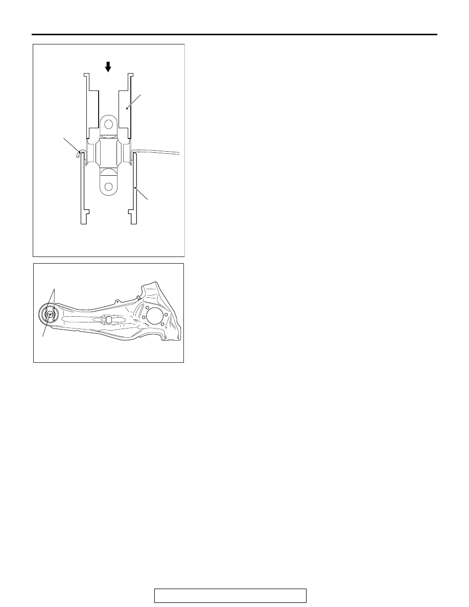
1. Use the special tools MB992121 and MB992125 to remove
the trailing arm bushing:
2. Determine the installation direction and the installation
position of the trailing arm bushing.
(1) Install so that the protruding side of the trailing arm
bushing inner pipe faces inside the body.
(2) Position horizontally the trailing arm bushing to body
connecting part, and locate bushing inner space as
shown in the figure.
AC506661AB
MB992121
MB992125
Trailing arm
Driving Out
AC612659AD
Bushing to body
connecting part
Bushing
inner space