Mitsubishi Outlander GS45X. Manual - part 1427


  Index      Mitsubishi     Mitsubishi Outlander GS45X - service repair manual


Search            


Content   ..  1425  1426  1427  1428   ..


Mitsubishi Outlander GS45X. Manual - part 1427


SRS AIR BAG DIAGNOSIS

TSB Revision

SUPPLEMENTAL RESTRAINT SYSTEM (SRS)

52B-203

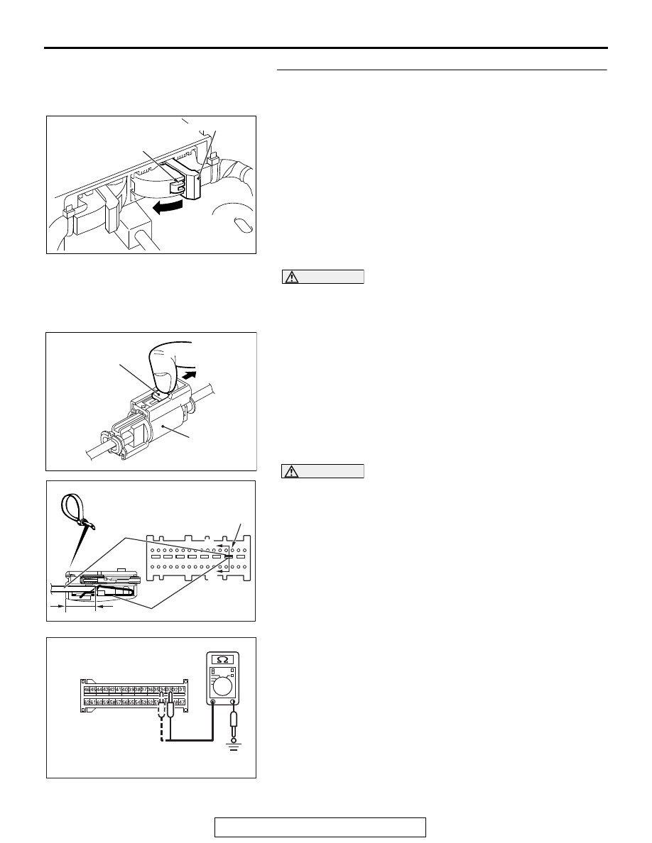
STEP 4. Check the side-air bag module (RH) circuit. 
Measure the resistance at the SRS-ECU connector C-27.
(1) Disconnect the negative battery terminal.
(2) While pushing the part "A" indicated in the figure of the 

harness side connector, turn the lock lever to the direction 
of the arrow to release the lock lever, and disconnect the 
C-27 SRS-ECU connector.

DANGER

To prevent the air bag from deploying unintentionally, 
disconnect the side-airbag module (RH) connector 
D-31 to short the squib circuit.

(3) Disconnect the D-31 side-airbag module connector, unlock 

the connector by sliding the locking button to the direction of 
the arrow as shown in the figure, and then disconnect the 
connector.

CAUTION

Insert an insulator such as a cable tie to a depth of 4mm 
(0.16 inch) or more, otherwise the short spring will not be 
released.
(4) Insert a cable tie [3 mm (0.12 inch) wide, 0.5 mm (0.02 inch) 

thick] between terminals 33, 34 and the short spring to 
release the short spring.

(5) Check for continuity between C-27 harness side connector 

terminals 33, 34 and body ground.
It should be an open circuit.

Q: Is it open circuit?

YES : Erase the diagnostic trouble code memory, and check 

the diagnostic trouble code. If DTC B1C2B sets, 
replace the SRS-ECU. (Refer to 

P.52B-436

). Then go 

to Step 6.

NO :  Go to Step 5.

AC507645

A

AC

Lock lever

AC706606

AI

Locking button

Side-airbag 

module

connector

AC507303AL

A

A

C-27 Harness side
connector (front view)

Section
A - A

Cable tie

Short spring

4 mm or more

Terminal

AC608812

C-27 Harness side 
connector (front view)

cv

SRS AIR BAG DIAGNOSIS

TSB Revision

SUPPLEMENTAL RESTRAINT SYSTEM (SRS)

52B-204

STEP 5. Check the harness wires for short circuit to 
ground between SRS-ECU connector C-27 (terminal No.33 
and 34) and side-air bag module (RH) connector D-31 
(terminal No.1 and 2).
Q: Is the check result normal?

YES : Go to Step 6.
NO :  Repair the harness wires between SRS-ECU 

connector C-27 and side-air bag module (RH) 
connector D-31. Then go to Step 6.

STEP 6. Recheck for diagnostic trouble code. 
Check again if the DTC is set.
(1) Erase the DTC.
(2) Turn the ignition switch to the "ON" position.
(3) Check if the DTC is set.
(4) Turn the ignition switch to the "LOCK" (OFF) position.
Q: Is DTC B1C2B set?

YES : Return to Step 1. 
NO :  The procedure is complete.

ZC501967

AC404789

AC701411AB

MB991824

MB991827

MB991910

Data link 
connector

SRS AIR BAG DIAGNOSIS

TSB Revision

SUPPLEMENTAL RESTRAINT SYSTEM (SRS)

52B-205

DTC B1C2C: Side-air bag Module (RH) (Squib) System (Shorted to Squib Circuit Power Supply)

CAUTION

If DTC B1C2C is set in the SRS-ECU, always diag-
nose the CAN bus lines.

.

CIRCUIT OPERATION

• The SRS-ECU judges how severe a collision is 

by detecting signals from the side impact sensor 
installed on the lower side of the center pillar. If 
the impact is over a predetermined level, the 
SRS-ECU sends an ignition signal. At this time, if 
the side collision safing G-sensor is on, the SRS 
air bag will inflate.

• The ignition signal is input to the side-air bag 

module to inflate the side-air bag.

.

DTC SET CONDITIONS

This DTC is set if there is abnormal resistance 
between the input terminals of the side-air bag mod-
ule (RH) (squib).

.

TROUBLESHOOTING HINTS

• Damaged wiring harnesses or connectors

• Short to the power supply in the side-air bag 

module (RH) (squib) harness

• Malfunction of the SRS-ECU

CONNECTOR
LOCK SWITCH

SRS-ECU

Side-Airbag Module (Squib) (RH) Circuit

CONNECTOR
LOCK SWITCH

: CONNECTOR COUPLED: ON
  CONNECTOR UNCOUPLED: OFF

NOTE

SIDE-AIRBAG
MODULE
(SQUIB) (RH)

AC901076

C-27 (Y)

AC

Connector: C-27

AC901079

Connector: D-31

AF

D-31 (Y)

SRS AIR BAG DIAGNOSIS

TSB Revision

SUPPLEMENTAL RESTRAINT SYSTEM (SRS)

52B-206

DIAGNOSIS

Required Special Tools:

• MB991958: Scan Tool (M.U.T.-III Sub Assembly)

• MB991824: Vehicle Communication Interface (V.C.I.)

• MB991827: M.U.T.-III USB Cable

• MB991910: M.U.T.-III Main Harness A (Vehicles with 

CAN Communication System)

• MB991865: Dummy resistor

• MB991866: Resister harness

STEP 1. Using scan tool MB991958, diagnose the CAN bus 
line.

CAUTION

To prevent damage to scan tool MB991958, always turn the 
ignition switch to the "LOCK" (OFF) position before con-
necting or disconnecting scan tool MB991958.
(1) Connect scan tool MB991958. Refer to "How to connect the 

scan tool 

P.52B-28

."

(2) Turn the ignition switch to "ON" position.
(3) Diagnose the CAN bus line.
(4) Turn the ignition switch to the "LOCK" (OFF) position.
Q: Is the check result satisfactory?

YES : Go to Step 2.
NO :  Repair the CAN bus line (Refer to GROUP 54C, 

Diagnosis 

P.54C-17

).

ZC501967

AC404789

AC701411AB

MB991824

MB991827

MB991910

Data link 
connector


Content   ..  1425  1426  1427  1428   ..