Mitsubishi Outlander GS45X. Manual - part 1215


  Index      Mitsubishi     Mitsubishi Outlander GS45X - service repair manual


Search            


Content   ..  1213  1214  1215  1216   ..


Mitsubishi Outlander GS45X. Manual - part 1215


GENERATOR AND DRIVE BELT

TSB Revision

ENGINE OVERHAUL <3.0L ENGINE>

11D-13

REMOVAL SERVICE POINT

.

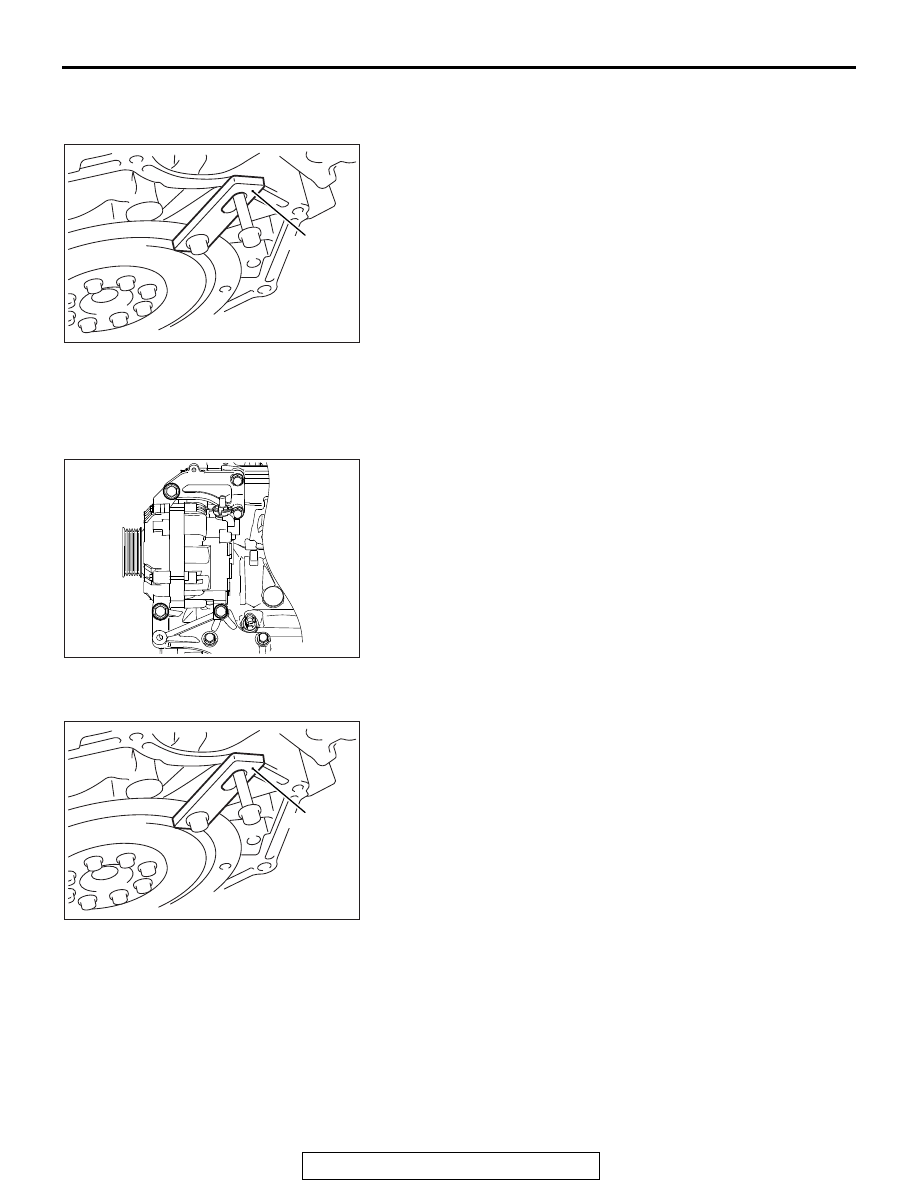
<<A>> CRANKSHAFT BOLT REMOVAL

1. Using special tool MD998781, hold the drive plate.
2. Remove the crankshaft bolt.

INSTALLATION SERVICE POINT

.

>>A<< GENERATOR INSTALLATION

1. Temporarily tighten the alternator to the alternator bracket.
2. In accordance with the tightening order shown in the 

illustration, tighten the installation bolts for the alternator to 
the specified torque.

Tightening torque: 47 

± 11 Nm (35 ± 7 ft-lb) 

.

>>B<< CRANKSHAFT BOLT INSTALLATION

1. Using special tool MD998781, hold the drive plate.

AK600940AC

MD998781

AK600845

1

2

3

AC

AK600940AC

MD998781

GENERATOR AND DRIVE BELT

TSB Revision

ENGINE OVERHAUL <3.0L ENGINE>

11D-14

2. Wipe the dirt on the crankshaft pulley washer using a rag.
3. Using a rag, wipe the dirt on the crankshaft pulley, the front 

flange, the crankshaft sprocket, the thread hole of the 
crankshaft and then remove the grease.

4. Install the front flange and crankshaft pulley.
5. Apply an appropriate and minimum amount of engine oil to 

the threads of crankshaft pulley centre bolt and lower part of 
the flange.

6. Install the crankshaft pulley washer to the crankshaft pulley 

centre bolt.

7. Tighten the crankshaft pulley centre bolt to 200 N

⋅m (148 

ft-lb).

8. Loosen the crankshaft pulley centre bolt fully.
9. Tighten the crankshaft pulley centre bolt to 110 N

⋅m (81 

ft-lb).

10.Make a paint mark on the crankshaft bolt.

CAUTION

• When the tightening angle is smaller than the specified 

tightening angle, the appropriate tightening capacity 
cannot be secured.

• When the tightening angle is larger than the specified 

tightening angle, remove the bolt to start from the 
beginning again according to the procedure.

11.Make a paint mark on the bolt end at a position 60 degrees 

from the paint mark made on the crankshaft pulley in the 
direction of tightening the crankshaft bolt.

12.Turn the crankshaft bolt another 60 degrees and make sure 

that the paint marks on the crankshaft pulley and crankshaft 
bolt are aligned.

AK602913

AG

Engine front

Crankshaft 
pulley centre bolt

Crankshaft
pulley washer

Crankshaft pulley

Crankshaft sprocket

Front frange

: Wipe clean with a rag.
: Wipe clean with a rag and degrease.
: Wipe clean with a rag, degrease and
  apply a small amount of engine oil.

Crankshaft

AK600939

60˚

AC

Crankshaft pulley

Crankshaft bolt

Paint mark

INTAKE MANIFOLD PLENUM AND THROTTLE BODY ASSEMBLY

TSB Revision

ENGINE OVERHAUL <3.0L ENGINE>

11D-15

INTAKE MANIFOLD PLENUM AND 

THROTTLE BODY ASSEMBLY

REMOVAL AND INSTALLATION

M1113003200176

AK900047AE

16

5

8

9

10

11

7

6

3

4

13

1

12

2

17

15

14

18

23 ± 6 N·m
17 ± 4 ft-lb

23 ± 6 N·m
17 ± 4 ft-lb

23 ± 6 N·m
17 ± 4 ft-lb

22 ± 1 N·m
16 ± 1 ft-lb

23 ± 6 N·m
17 ± 4 ft-lb

23 ± 6 N·m
17 ± 4 ft-lb

23 ± 6 N·m
17 ± 4 ft-lb

5.0 ± 1.0 N·m
45 ± 8 in-lb

5.0 ± 1.0 N·m
45 ± 8 in-lb

Removal steps 

1. Exhaust gas recirculation pipe

>>E<<

2. Exhaust gas recirculation pipe gasket
3. Exhaust gas recirculation pipe gasket
4. Harness bracket
5. Throttle body

>>D<<

6. Throttle body gasket

7. Vacuum hose
8. Solenoid valve 
9. O-ring
10. Boost sensor
11. O-ring
12. Purge hose

Removal steps (Continued)

INTAKE MANIFOLD PLENUM AND THROTTLE BODY ASSEMBLY

TSB Revision

ENGINE OVERHAUL <3.0L ENGINE>

11D-16

INSTALLATION SERVICE POINT

.

>>A<< INTAKE MANIFOLD PLENUM STAY, REAR 
INSTALLATION

1. After temporarily tightening the rear intake manifold plenum 

stay with the installation bolts, check that the intake manifold 
fastens securely to the cylinder head.

2. Tighten the rear intake manifold plenum stay to the specified 

torque.

Tightening torque: 23 

± 6 Nm (17 ± 4 ft-lb)

.

>>B<< INTAKE MANIFOLD PLENUM STAY, FRONT 
INSTALLATION

1. After temporarily tightening the front manifold plenum stay 

with the installation bolts, check that the intake manifold 
fastens securely to the cylinder head.

2. Tighten the front manifold plenum stay to the specified 

torque.

Tightening torque: 23 

± 6 Nm (17 ± 4 ft-lb)

.

>>C<< THROTTLE BODY STAY INSTALLATION

1. After temporarily tightening the throttle body stay with the 

installation bolts, check that the throttle body fastens 
securely to the cylinder head.

2. Tighten the throttle body stay to the specified torque.

Tightening torque: 23 

± 6 Nm (17 ± 4 ft-lb)

.

>>C<<

13. Throttle body stay
14. Engine hanger, right

>>B<<

15. Intake manifold plenum stay, front

>>A<<

16. Intake manifold plenum stay, rear
17. Intake manifold plenum
18. Intake manifold plenum gasket

Removal steps (Continued)

AK900036


AC

Intake manifold 
plenum stay, rear

AK900037AC

Intake manifold
plenum stay, front

AK900038 AC

Throttle body
stay


Content   ..  1213  1214  1215  1216   ..