Mitsubishi Outlander GS45X. Manual - part 109


  Index      Mitsubishi     Mitsubishi Outlander GS45X - service repair manual


Search            


Content   ..  107  108  109  110   ..


Mitsubishi Outlander GS45X. Manual - part 109


REAR VIEW CAMERA

TSB Revision

CHASSIS ELECTRICAL

54A-433

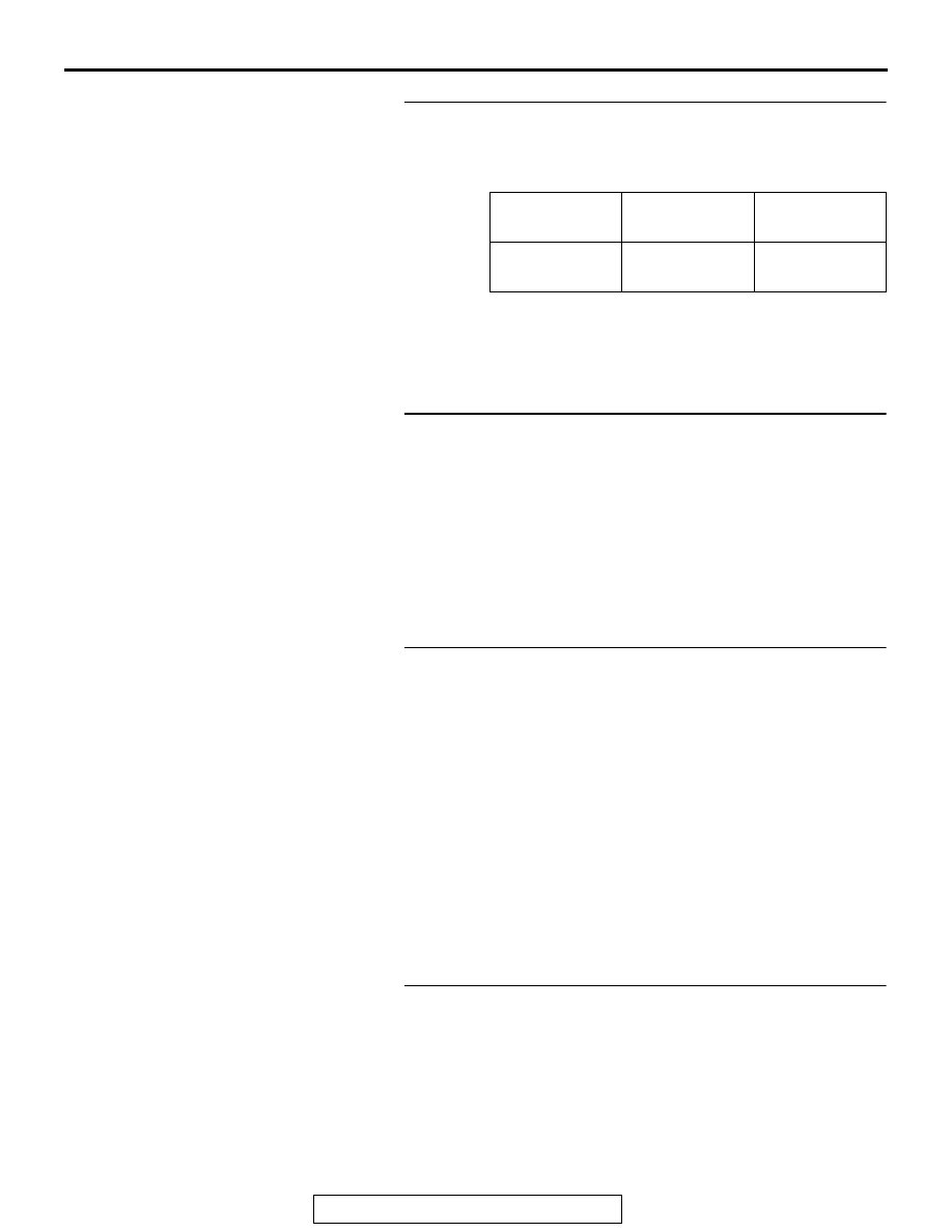
STEP 3. Using scan tool MB991958, check data list
Check if ETACS-ECU related signal is set.

• Turn the ignition switch to the ON position.

• selector lever is "R" (Reverse) position

OK: Normal condition is displayed.

Q: Is the check result normal?

YES : Go to step 10.
NO :  Go to step 4.

STEP 4. Check ETACS-ECU connector C-313 and 
transmission range switch connector B-110 for loose, 
corroded or damaged terminals, or terminals pushed back 
in the connector.
Q: Are ETACS-ECU connector C-313 and transmission 

range switch connector B-110 in good condition?
YES : 
Go to Step 5.
NO :  Repair or replace the damaged component(s). Refer 

to GROUP 00E, Harness Connector Inspection 

P.00E-2

.

STEP 5. Check the wiring harness between ETACS-ECU 
connector C-313 (terminal 4) and transmission range 
switch connector B-110 (terminal 3).

• Check the communication lines for open circuit and short 

circuit.

NOTE: Also check intermediate connector C-129, A-13 for 
loose, corroded, or damaged terminals, or terminals pushed 
back in the connector. If intermediate connector C-129, A-13 is 
damaged, repair or replace the connector as described in 
GROUP 00E, Harness Connector Inspection 

P.00E-2

.

Q: Is the wiring harness between ETACS-ECU connector 

C-313 (terminal 4) and transmission range switch 
connector B-110 (terminal 3) in good condition?
YES : 
Go to Step 6.
NO :  Repair the wiring harness.

STEP 6. Check ETACS-ECU connector C-304 for loose, 
corroded or damaged terminals, or terminals pushed back 
in the connector.
Q: Is ETACS-ECU connector C-304 in good condition?

YES : Go to Step 7.
NO :  Repair or replace the damaged component(s). Refer 

to GROUP 00E, Harness Connector Inspection 

P.00E-2

.

Item No.

Item name

Normal 
condition

289

shift reveres 
SW

ON

REAR VIEW CAMERA

TSB Revision

CHASSIS ELECTRICAL

54A-434

STEP 7. Check the wiring harness between ETACS-ECU 
connector C-304 (terminal 2) and transmission range 
switch connector B-110 (terminal 9).

• Check the communication lines for open circuit and short 

circuit.

NOTE: Also check intermediate connector A-13 for loose, cor-
roded, or damaged terminals, or terminals pushed back in the 
connector. If intermediate connector A-13 is damaged, repair or 
replace the connector as described in GROUP 00E, Harness 
Connector Inspection 

P.00E-2

.

Q: Is the wiring harness between ETACS-ECU connector 

C-304 (terminal 2) and transmission range switch 
connector B-110 (terminal 9) in good condition?
YES : 
Go to Step 8.
NO :  Repair the wiring harness.

STEP 8. Check the transmission range switch and the 
control cable.
Check that the transmission range switch and the control cable 
are adjusted correctly.(GROUP 23A

− On-vehicle Service, 

transmission range switch and control cable adjustment 

P.23A-144

 <CVT> or GROUP 23C 

− On-vehicle Service, trans-

mission range switch and control cable adjustment

P.23C-269


<A/T>)
Q: Is the check result normal?

YES : Go to Step 9.
NO :  Adjust the transmission range switch and the control 

cable.

STEP 9. Check the transmission range switch.

• Check for continuity of the transmission range switch. 

(Refer to GROUP 23A 

− On-vehicle service, Transmission 

range check 

P.23A-143

 <CVT> or GROUP 23C 

− On-vehi-

cle service, Transmission range check 

P.23C-269

 <A/T>)

Q: Is the check result normal?

YES : The trouble can be an intermittent malfunction (Refer 

to GROUP 00 

− How to use 

Troubleshooting/inspection Service Points 

− How to 

Cope with Intermittent Malfunction 

P.00-15

).

NO :  Replace the transmission range switch.

STEP 10. Check ETACS-ECU connector C-311 and 
multivision display connector C-09 for loose, corroded or 
damaged terminals, or terminals pushed back in the 
connector.
Q: Are ETACS-ECU connector C-311 and multivision 

display connector C-09 in good condition?
YES : 
Go to Step 11.
NO :  Repair the defective connector.

REAR VIEW CAMERA

TSB Revision

CHASSIS ELECTRICAL

54A-435

STEP 11. Check the wiring harness between ETACS-ECU 
C-311 connector (terminal 2) and C-09 multivision display 
connector (terminal 24).

• Check the communication lines for open circuit or short cir-

cuit.

NOTE: Before the wiring harness inspection, inspect the C-19 
and C-32 intermediate connector, and repair if necessary.
Q: Is the wiring harness between ETACS-ECU C-311 

connector (terminal 2) and C-09 multivision display 
connector (terminal 24) in good condition?
YES : 
Go to step 12.
NO :  Repair the wiring harness.

STEP 12. Confirmation in MMCS service mode
Perform "Network/Connect Line Check" in the MMCS service 
mode to check that the communication and wire connection 
with the rear view camera are OK (Refer to 

P.54A-443

).

NOTE: The rear view camera is shown as "rear camera" on the 
"Network/Connect Line Check" in the service mode of MMCS.
Q: Is the check result normal?

YES : Go to Step 14.
NO :  Go to Step 13.

STEP 13. Check rear view camera connector F-21 and 
multivision display connector C-39 for loose, corroded or 
damaged terminals, or terminals pushed back in the 
connector.
Q: Are rear view camera connector F-21 and multivision 

display connector C-39 in good condition?
YES : 
Go to Step 14.
NO :  Repair the defective connector.

STEP 14. Check the wiring harness between rear view 
camera connector F-21 connector (terminal 6, 2, 5, 4) and 
multivision display C-39 connector (terminal 93, 91, 92, 96)

• Check the communication lines for open circuit and short 

circuit.

NOTE: Also check intermediate connector C-19, C-22, D-38 for 
loose, corroded, or damaged terminals, or terminals pushed 
back in the connector. If intermediate connector C-19, C-22, 
D-38 is damaged, repair or replace the connector as described 
in GROUP 00E, Harness Connector Inspection 

P.00E-2

.

Q: Is the check result normal?

YES : Go to Step 15.
NO :  Repair the wiring harness.

REAR VIEW CAMERA

TSB Revision

CHASSIS ELECTRICAL

54A-436

STEP 15. Confirmation in MMCS service mode.
(1) Display the VEHICLE SIGNAL CHECK screen. (Refer to 

P.54A-443

.)

(2) Move the selector lever to the R position and check whether 

"ON" is displayed.

Q: Is the check result normal?

YES : Go to Step 16.
NO :  Replace the multivision display.

STEP 16. Trouble symptom recheck
Check that the display of rear view camera is shown normally.
Q: Is the check result normal?

YES : The trouble can be an intermittent malfunction (Refer 

to GROUP 00 

− How to use 

Troubleshooting/inspection Service Points 

− How to 

Cope with Intermittent Malfunction 

P.00-15

).

NO :  Replace the rear view camera temporarily and go to 

Step 17.

STEP 17. Trouble symptom recheck
Check that the display of rear view camera is shown normally.
Q: Is the check result normal?

YES : Replace the rear view camera.
NO :  Replace the multivision display.

ON-VEHICLE SERVICE

CAMERA SETTING

M1540905700019

Refer to MMCS 

− service mode 

P.54A-443

.

REMOVAL AND INSTALLATION

M1540905500059

AC612375AB

1

2

1.5 ± 0.5 N·m
13 ± 4 in-lb

Removal Steps 

Liftgate trim (Refer to GROUP 52A 
− Liftgate Trim 

P.52A-14

)

1.

Rear view camera

2.

Screw grommet

Removal Steps (Continued)

Next>>


Content   ..  107  108  109  110   ..