Mitsubishi Outlander (2013+). Manual - part 758
INSTRUMENT PANEL
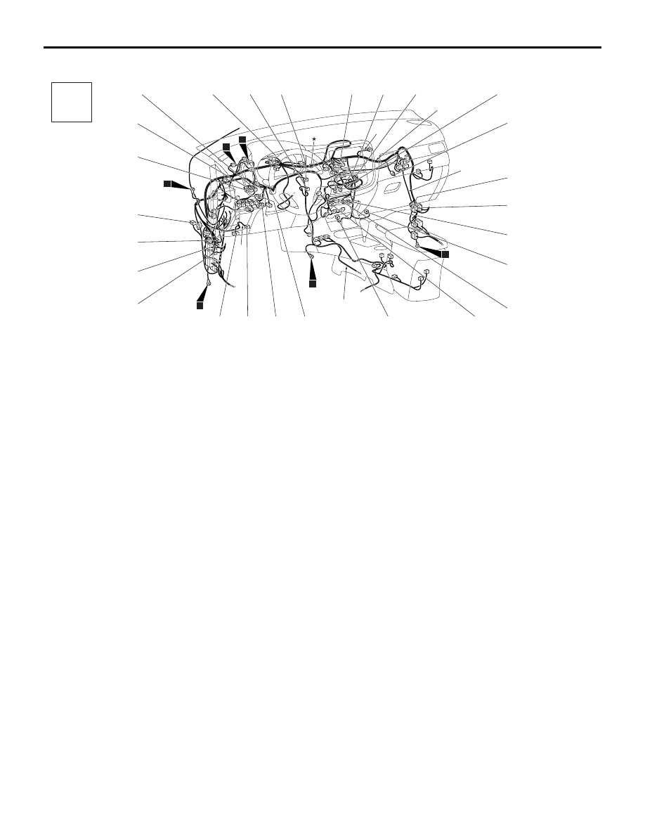
CONFIGURATION DIAGRAMS
80-8
INSTRUMENT PANEL (CONTINUED)
ACB04395
Connector
symbol
-201
thru
-226
C
AD
Connector colour
code
B : Black
BR : Brown
G : Green
GR : Grey
L : Blue
None : Milk white
O : Orange
R : Red
V : Violet
Y : Yellow
Y
Instrument panel
wiring harness
Front wiring
harness
Floor wiring
harness
Y
2
4
16
17
18
19
C-201
C-202
C-203
C-204
C-205
C-206
C-207
C-208
C-209
C-210
C-211
C-212
C-227
C-213
C-214
C-215
C-216
C-217
C-218
C-219
C-220
C-221
C-222
C-223
C-224
C-225
C-226
C-201 (8-B)
Meter information switch
C-202 (22-B)
J/C (2)
C-203 (2)
Interior temperature sensor
C-204 (10)
Engine switch <Vehicles with KOS>
C-205 (32-GR) Heater controller assembly (A/C-ECU)
C-206 (20-GR) Heater controller assembly (A/C-ECU)
C-207 (5-G)
Outside/inside air selection damper
control motor
C-208 (5-G)
Mode selection damper control motor
C-209 (2-B)
Glove box lamp
C-210 (22)
Instrument panel wiring harness and
front door wiring harness (RH)
combination
C-211 (16)
Instrument panel wiring harness and
front door wiring harness (RH)
combination
C-212 (5-G)
Air mixing damper control motor (RH)
<Vehicles with dual-zone auto A/C>
C-213 (2)
Blower motor
C-214 (2)
Fin thermo sensor
C-215 (5-G)
Air mixing damper control motor (LH)
<Vehicles with dual-zone auto A/C>
C-216 (4)
Power transistor
C-217 (2-B)
EPS-ECU
C-218 (4)
EPS-ECU
C-219 (2-B)
Driver's knee air bag module (squib)
C-220 (16-B)
Diagnosis connector
C-221 (16)
Instrument panel wiring harness and
front door wiring harness (LH)
combination
C-222 (22-B)
Instrument panel wiring harness and
front door wiring harness (LH)
combination
C-223 (20)
Instrument panel wiring harness and
roof wiring harness combination
C-224 (16)
4WD-ECU
C-225 (10-GR) Headlamp manual levelling switch
C-226 (5-L)
ASC off switch
C-227 (5-G)
Air mixing damper control motor
<Vehicles with single-zone auto A/C>