Mitsubishi Outlander (2013+). Manual - part 688
MITSUBISHI MULTI COMMUNICATION SYSTEM (MMCS)
CHASSIS ELECTRICAL
54A-237
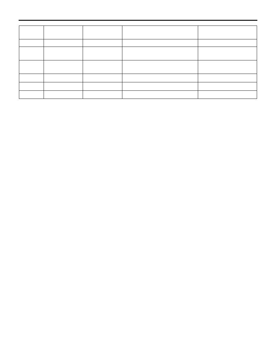
7
GND
GND
Always
1 V or less
8
SH-C
SHIELD (CAN
BOX DATA)
Always
1 V or less
9
CK-C
CAN BOX DATA
CLK
Ignition switch: ACC position
1 - 5V (DC)
10
− 12
−
−
−
−
13
CAN-
CAN-L
−
−
14
CAN+
CAN-H
−
−
Terminal
No.
Signal symbol
Check item
Check condition
Terminal voltage