Mitsubishi Outlander (2013+). Manual - part 687
RADIO AND CD PLAYER
CHASSIS ELECTRICAL
54A-233
STEP 2. Check the illumination.
When the tail lamps are turned on, check whether
the illumination other than the radio and CD player is
turned on.
Q: Is the check result normal?
YES :
Go to Step 3.
NO :
Replace the heater controller assembly
(A/C-ECU).
STEP 3. Check of short to power supply, short to
earth, and open circuit in ILL+ line between radio
and CD player connector and heater controller
assembly (A/C-ECU) connector
Q: Is the check result normal?
YES :
Go to Step 4.
NO :
Repair the connector(s) or wiring harness.
STEP 4. Retest the system
When the tail lamps illuminate, check that the illumi-
nation of the radio and CD player is switched from
day mode to night mode.
Q: Is the check result normal?
YES :
The trouble can be an intermittent
malfunction (Refer to GROUP 00
− How to
use Troubleshooting/inspection Service
Points
− How to Cope with Intermittent
Malfunction ).
NO :
Replace the radio and CD player.
RADIO AND CD PLAYER
REMOVAL AND INSTALLATION
M1544011300428
NOTE: When the radio and CD player is replaced, always turn the ignition switch to the "ON" position once
and then carry out the operation check.
Pre-removal Operation
• Centre Panel Assembly Removal (Refer to GROUP 52A −
Instrument Panel Assembly ).
Post-installation Operation
• Centre Panel Assembly Installation (Refer to GROUP 52A
− Instrument Panel Assembly ).
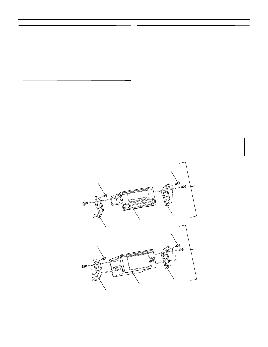
ACB05389
AB
1
1
0.5 N·m
0.5 N·m
3
2
0.5 N·m
0.5 N·m
4
3
2
4
<Vehicles with 1CD audio>
<Vehicles with display audio>
Removal steps
1.
Radio and CD player assembly
2.
Radio and CD player bracket LH
3.
Radio and CD player bracket RH
4.
Radio and CD player
REMOVAL AND INSTALLATION
M1549101300366
For the USB cable removal and installation proce-
dures, refer to