Mitsubishi Outlander (2013+). Manual - part 621


  Index      Mitsubishi     Mitsubishi Outlander - service repair manual 2013 year


Search            


Content   ..  619  620  621  622   ..


Mitsubishi Outlander (2013+). Manual - part 621


DRIVER'S AIR BAG MODULE AND CLOCK SPRING

SUPPLEMENTAL RESTRAINT SYSTEM (SRS)

52B-135

INSPECTION

M1524047600280

DRIVER'S AIR BAG MODULE

CAUTION

• Never measure circuit resistance in the air 

bag modules (squib) even with the specified 
tester. Measuring the circuit resistance with a 
tester causes accidental air bag deployment 
due to current that flows or static, resulting in 
serious personal injury.

• When replacing the parts, discard the old 

parts after deploying the air bag according to 
the specified procedure (Refer to 

P.52B-152

).

If any malfunction is found in the following inspec-
tions, replace the air bag module with a new one.

ACB03701AC

Squib 
connectors

Inflator

1. Pad cover dent, crack or deformation
2. Check the harness and connector for damage 

and the terminal for deformation.

3. Check the air bag inflator cases for dents, cracks 

or deformation.

4. Check the air bag module for proper installation.
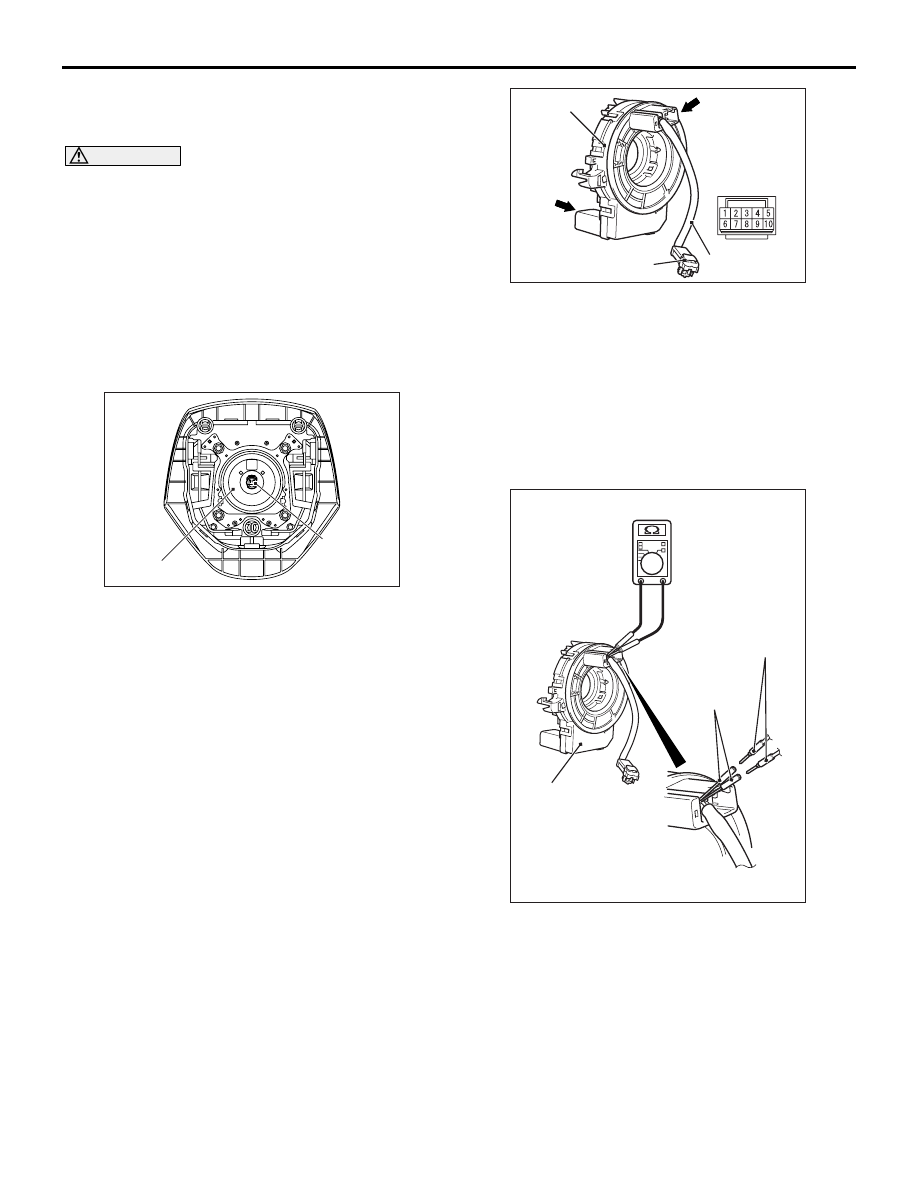
CLOCK SPRING

If any malfunction is found in the following inspec-
tions, replace the clock spring with a new one.

AC904942 AG

Case

Clock 
spring
connector

Clock spring
connector

Driver's air bag 

module connector

Horn connector

Horn connector

Protective tube

1. Check the connectors and protective tubes for 

damage and the terminal for deformation.

2. Check the case for damage.

3. Check that the continuity exists between the 

following connector terminals.

• Clock spring connector terminal 1 and horn con-

nector terminal 1

• Clock spring connector terminal 5 and horn con-

nector terminal 5

AC905415AC

Clock spring

Digital
multi-meter

Extra fine probe
(MB992006)

4. As shown in the Figure, connect the circuit tester 

to special tool extra fine probe (MB992006) and 
check to see that there is a charge between the 
terminals.

PASSENGER'S (FRONT) AIR BAG MODULE

SUPPLEMENTAL RESTRAINT SYSTEM (SRS)

52B-136

PASSENGER'S (FRONT) AIR BAG MODULE

REMOVAL AND INSTALLATION

M1524047300386

CAUTION

• Disconnect the negative () battery terminal and wait for 60 seconds or more before starting work. 

Insulate the disconnected (

)terminal by wrapping the tape (Refer to the item 5 of Service Precau-

tions 

P.52B-7

).

• Never attempt to disassemble or repair the air bag module. If faulty, replace it with new one.
• Do not drop the air bag module or allow contact with water, grease or oil. If denting, cracking, or 

deformation is discovered, replace it with new one.

• Store the air bag modules on a flat surface with the deployment surface facing up. Also, do not put 

anything on it.

• Do not store the air bag module in a place more than 93°C.
• When the air bags have been deployed, replace the and air bag module with new one.
• Put on gloves and safety glasses when handling deployed air bags.
• When discarding the air bag module, make sure to deploy the air bag before the disposal (Refer to 

P.52B-152

).

Pre-removal operation
• Turn ignition switch to the LOCK (OFF) position.

• Disconnect the negative (−) battery terminal.

ACB05622

AB

3

2

1

5.0 ± 1.0 N·m

Removal steps 

Upper glove box assembly (Refer 
to GROUP 52A 

− Instrument Panel 

Assembly ).

<<

A

>>

1.

Passenger’s (front) air bag module 
connector

2.

Bolts

Instrument panel assembly (Refer 
to GROUP 52A 

− Instrument Panel 

Assembly ).

<<

B

>>

3.

Passenger’s (front) air bag module

Installation steps 

>>

A

<<

Pre-installation inspection

3.

Passenger’s (front) air bag module

Instrument panel assembly (Refer 
to GROUP 52A 

− Instrument Panel 

Assembly ).

2.

Bolts

1.

Passenger’s (front) air bag module 
connector

Upper glove box assembly (Refer 
to GROUP 52A 

− Instrument Panel 

Assembly ).

>>

B

<<

Post-installation inspection

PASSENGER'S (FRONT) AIR BAG MODULE

SUPPLEMENTAL RESTRAINT SYSTEM (SRS)

52B-137

REMOVAL SERVICE POINTS

<<A>> PASSENGER'S (FRONT) AIR BAG 
MODULE CONNECTOR REMOVAL

ACB04307AB

Passenger's air bag module 

harness side connector

Locking button

Flat-tipped
screwdriver

Use the flat-tipped screwdriver to pull out the locking 
button of wiring harness side connector, and release 
the lock.

<<B>> PASSENGER'S (FRONT) AIR BAG 
MODULE REMOVAL

CAUTION

• Never use an electric tester to diagnose the 

air bag module circuit. Never attempt to dis-
assemble the air bag module.

• The removed passenger's air bag module 

should be stored in a clean, dry place with the 
deployment surface facing up.

• When discarding the air bag module, discard 

after deploying the air bag as specified in the 
service procedure (Refer to 

P.52B-152

).

ACA00360

Flat-tipped 
screwdriver

Passenger's (front) 
air bag module

AB

Insert a flat-tipped screwdriver or similar tool to the 
location shown in the figure. After disengaging the 
tabs, remove the passenger's (front) air bag module.

INSTALLATION SERVICE POINTS

>>A<< PRE-INSTALLATION INSPECTION

1. Before the installation, check the air bag module 

(Refer to 

P.52B-137

).

NOTE: Even when installing a new air bag mod-
ule, perform an inspection before the installation.

2. Connect the negative (

−) battery terminal.

CAUTION

Be sure to turn the ignition key to the LOCK 
(OFF) position when connecting or disconnect-
ing M.U.T.-III.

3. Connect M.U.T.-III to the diagnosis connector (16 

pin).

4. Turn the ignition switch to the ON position.

5. Read the diagnosis code, and check that 

everything is normal except the air bag module 
open circuit.

6. Turn the ignition switch to the LOCK (OFF) 

position.

>>B<< POST-INSTALLATION 
INSPECTION

1. Connect the negative (

−) battery cable.

2. Turn the ignition switch to the "ON" position.

ACC00038AB

SRS warning lamp

3. Check that the SRS warning lamp is illuminated 

for 6 to 8 seconds, and extinguished afterward.

4. If the lamp does not extinguish, perform the 

troubleshooting (Refer to 

P.52B-13

).

INSPECTION

M1524047400145

CAUTION

• Never measure circuit resistance in the air 

bag modules (squib) even with the specified 
tester. Measuring the circuit resistance with a 
tester causes accidental air bag deployment 
due to current that flows or static, resulting in 
serious personal injury.

• When replacing the parts, discard the old 

parts after deploying the air bag according to 
the specified procedure (Refer to 

P.52B-152

).

If any malfunction is found in the following inspec-
tions, replace the air bag module with a new one.

ACB05537AB

Squib connectors

Inflator

PASSENGER'S (FRONT) AIR BAG MODULE

SUPPLEMENTAL RESTRAINT SYSTEM (SRS)

52B-138

1. Check the harness and connector for damage and 

the terminal for deformation.

2. Check the air bag inflator cases for dents, cracks 

or deformation.

3. Check the air bag module for proper installation.


Content   ..  619  620  621  622   ..