Mitsubishi Outlander (2013+). Manual - part 620


  Index      Mitsubishi     Mitsubishi Outlander - service repair manual 2013 year


Search            


Content   ..  618  619  620  621   ..


Mitsubishi Outlander (2013+). Manual - part 620


DRIVER'S AIR BAG MODULE AND CLOCK SPRING

SUPPLEMENTAL RESTRAINT SYSTEM (SRS)

52B-131

DRIVER'S AIR BAG MODULE AND CLOCK SPRING

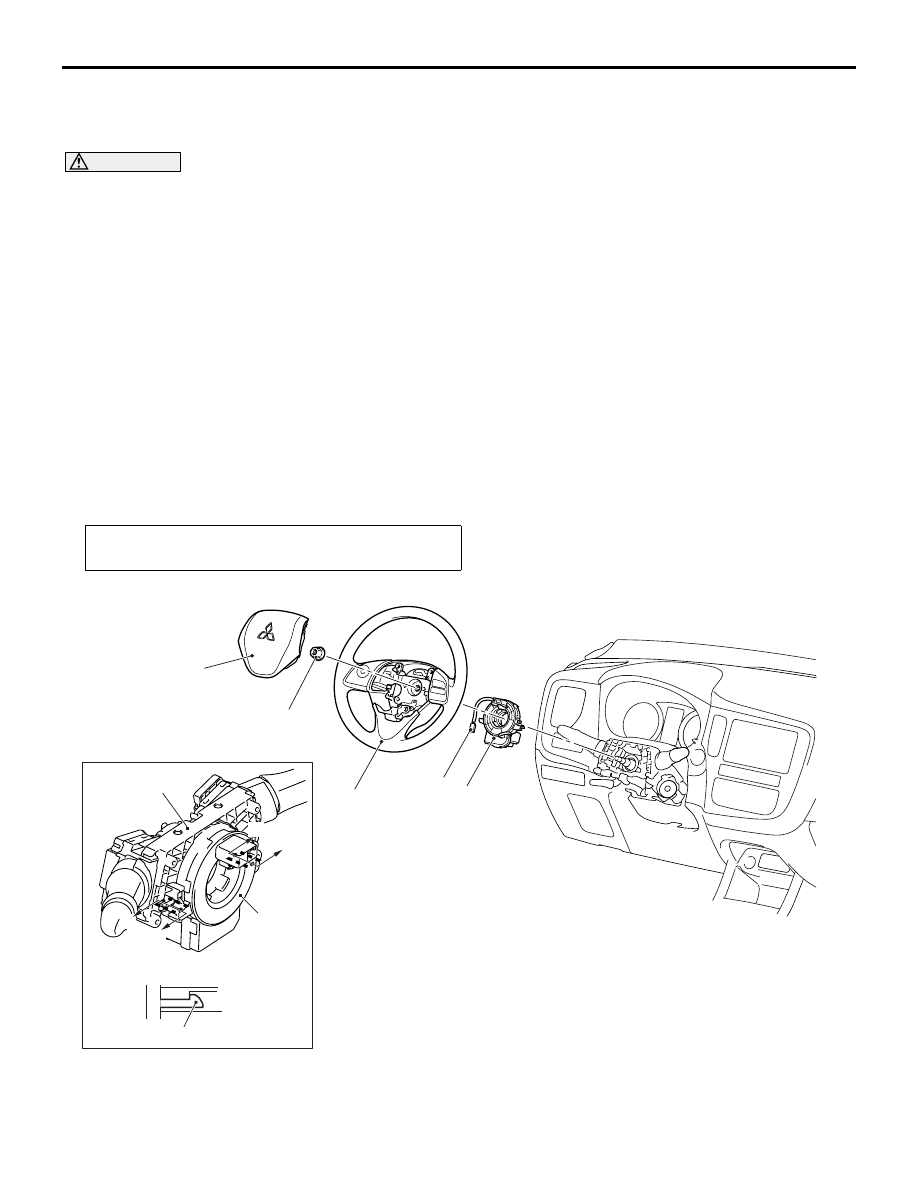
REMOVAL AND INSTALLATION

M1524047500692

CAUTION

• Disconnect the negative () battery terminal and wait for 60 seconds or more before starting work. 

Insulate the disconnected (

)terminal by wrapping the tape (Refer to the item 5 of Service Precau-

tions ).

• Never attempt to disassemble or repair the air bag module and clock spring. If faulty, replace it 

with new one.

• Do not drop the air bag module or clock spring or allow contact with water, grease or oil. If dent-

ing, cracking, or deformation is discovered, replace it with new one.

• Store the air bag module on a flat surface with the deployment surface facing up. Also, do not put 

anything on it.

• Do not store the air bag module in a place more than 93°C.
• When the driver's air bag have been deployed, replace the driver's air bag module with new one. 

Also, check the clock spring, and replace with a new part if there is an abnormality.

• Put on gloves and safety glasses when handling deployed air bag.
• When discarding the air bag module, make sure to deploy the air bag before the disposal (Refer to 

P.52B-152

).

Pre-removal operation
• Disconnect the negative (−) battery terminal.

AC905017

ACC00146

ACB05621

A

A

Column switch

Section A - A

Claw

AB

A

A

1

2

3

4

4

44 ± 11 N·m

Driver's air bag module removal 
steps 

<<

A

>>

1.

Driver's air bag module

<<

B

>>

2.

Driver's air bag module connector

Driver's air bag module 
installation steps 

>>

A

<<

Pre-installation inspection

2.

Driver's air bag module connector

DRIVER'S AIR BAG MODULE AND CLOCK SPRING

SUPPLEMENTAL RESTRAINT SYSTEM (SRS)

52B-132

<<A>> DRIVER'S AIR BAG MODULE 
REMOVAL

CAUTION

• Never use an electric tester to diagnose the 

air bag module circuit. Never attempt to dis-
assemble the air bag module.

• Be sure to store the removed air bag module 

in a clean and dry place with a pad surface 
facing upward.

• When discarding the air bag module, discard 

after deploying the air bag as specified in the 
service procedure (Refer to 

P.52B-152

).

ACB04378

ACB04269

ACB04270

ACB04271

ACB04272 

AB

Driver's air bag module

Steering wheel assembly

Rod

Flat-tipped
screwdriver

Flat-tipped
screwdriver

Flat-tipped
screwdriver

1

2

3

Service hole

Service hole

Service hole

Follow the procedure below according to the item 
numbers in the illustration.
1. Insert a flat-tipped screwdriver into the service 

hole on the steering wheel assembly.

2. Use the flat-tipped screwdriver to press the rod in 

driver’s air bag module. 

3. When the driver’s air bag module is disengaged, 

the driver’s air bag module will be released.

4. Repeat for the other service hole end then 

remove the driver’s air bag module.

1.

Driver's air bag module

>>

D

<<

Post-installation inspection
Clock spring removal steps 

<<

A

>>

1.

Driver's air bag module

<<

B

>>

2.

Driver's air bag module connector

<<

C

>>

3.

Steering wheel assembly

Steering column lower, upper cover 
(Refer to GROUP 37 

−Steering 

Column Shaft Assembly ).

<<

D

>>

4.

Clock spring
Clock spring installation steps 

>>

A

<<

Pre-installation inspection

>>

B

<<

4.

Clock spring

Steering column lower, upper cover 
(Refer to GROUP 37 

− Steering 

Column Shaft Assembly  <.

>>

C

<<

3.

Steering wheel assembly

2.

Driver's air bag module connector

1.

Driver's air bag module

>>

D

<<

Post-installation inspection

Driver's air bag module 
installation steps (Continued)

Clock spring installation steps 

DRIVER'S AIR BAG MODULE AND CLOCK SPRING

SUPPLEMENTAL RESTRAINT SYSTEM (SRS)

52B-133

<<B>> DRIVER'S AIR BAG MODULE 
CONNECTOR REMOVAL

ACB04316 AB

Driver's air bag module 
harness side connector

Locking button

Flat-tipped
screwdriver

1. Use the flat-tipped screwdriver to pull out the 

locking button of wiring harness side connector, 
and release the lock.

<<C>> STEERING WHEEL ASSEMBLY 
REMOVAL

CAUTION

Use the special tool to remove the steering wheel 
since the steering column collision absorbing 
mechanism may be damaged.

1. Position the steering wheel in a straight ahead 

direction.

AC607307

MB990803

AB

2. Using special tool steering wheel puller 

(MB990803), remove the steering wheel 
assembly as shown in the figure.

<<D>> CLOCK SPRING REMOVAL

CAUTION

The removed clock spring should be stored in a 
clean, dry place.

AC904863

ACB04903

Connector lock

Clock spring

AB

Lift the connector lock of clock spring connector to 
the direction of the arrow, then unlock and discon-
nect the connector.

INSTALLATION SERVICE POINTS

>>A<< PRE-INSTALLATION INSPECTION

1. Before the installation, check the air bag module 

and clock spring (Refer to 

P.52B-135

).

NOTE: Even when installing a new air bag mod-
ule or clock spring, perform an inspection before 
the installation.

2. Connect the negative (

−) battery terminal.

CAUTION

Be sure to turn the ignition key to the LOCK 
(OFF) position when connecting or disconnect-
ing M.U.T.-III.

3. Connect M.U.T.-III to the diagnosis connector (16 

pin).

4. Turn the ignition switch to the ON position.

5. Read the diagnosis code, and check that 

everything is normal except the air bag module 
open circuit.

6. Turn the ignition switch to the LOCK (OFF) 

position.

DRIVER'S AIR BAG MODULE AND CLOCK SPRING

SUPPLEMENTAL RESTRAINT SYSTEM (SRS)

52B-134

>>B<< CLOCK SPRING INSTALLATION

CAUTION

• If the centre of the clock spring is not cor-

rectly aligned, the steering wheel may not be 
turned fully or the cable inside the clock 
spring may be broken, causing the SRS air-
bag to be inoperative or operated incorrectly.

• When aligning the clock spring neutral posi-

tion mark, perform with the clock spring inde-
pendently. If performed with the steering 
wheel sensor installed, the steering wheel 
sensor may be damaged.

AC904940

AD

Mark for 
checking 
neutral point 

Mating marks

Align the mating marks of the clock spring.

<Alignment of mating marks>
(1) Turn the clock spring clockwise fully.
(2) Turn the clock spring anti-clockwise 

approximately two and 9/10 turns to align the 
mating marks.

(3) Check that the orange roller can be seen from 

the window for checking the neutral point 
when the mating marks are aligned.

NOTE: If the orange roller cannot be seen or 
black roller can be seen, the neutral point is not 
aligned correctly.

(4) Install the clock spring to the column switch.

>>C<< STEERING WHEEL ASSEMBLY 
INSTALLATION

CAUTION

When installing the steering wheel assembly, do 
not trap the clock spring harness.

AC905462

AC

Rib for engagement 
with steering 
wheel assembly

1. After checking that the clock spring centre 

alignment is already performed, install the 
steering wheel assembly so that its boss part is 
aligned with the rib of the clock spring slowly.

2. After the installation, check that there is no 

abnormality when the steering wheel is fully 
turned to left and right.

>>D<< POST-INSTALLATION 
INSPECTION

1. Connect the negative (

−) battery cable.

2. Turn the ignition switch to the "ON" position.

ACC00038AB

SRS warning lamp

3. Check that the SRS warning lamp is illuminated 

for 6 to 8 seconds, and extinguished afterward.

4. If the lamp does not extinguish, perform the 

troubleshooting (Refer to 

P.52B-13

).


Content   ..  618  619  620  621   ..