Mitsubishi Outlander (2013+). Manual - part 619
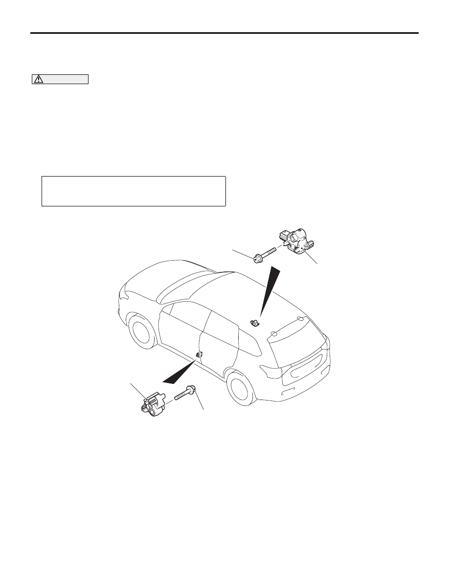
SIDE IMPACT SENSOR
SUPPLEMENTAL RESTRAINT SYSTEM (SRS)
52B-127
SIDE IMPACT SENSOR
REMOVAL AND INSTALLATION
M1524004601462
CAUTION
• Disconnect the negative (−) battery terminal and wait for 60 seconds or more before starting work.
Insulate the disconnected (
−) terminal by wrapping the tape (Refer to the item 5 of Service Precau-
• Never attempt to disassemble or repair the side impact sensor. If damaged, replace it with new
one(s).
• Handle the side impact sensor with sufficient caution, and do not drop or subject the sensor to
impact or vibration. If there is a dent, crack, or deformation, replace with a new sensor.
•
Pre-removal operation
• Turn the ignition switch to the LOCK (OFF) position.
• Disconnect the negative (−) battery terminal.
ACB05458AB
10 ± 2 N·m
10 ± 2 N·m
1
1
Side impact sensor removal
steps
•
Centre pillar trim lower (Refer to
GROUP 52A
− Interior Trim ).
•
Seat belt with pre-tensioner (Refer
to
1.
Side impact sensor
Side impact sensor installation
steps
>>
A
•
Pre-installation inspection
>>
B
1.
Side impact sensor
•
Seat belt with pre-tensioner (Refer
to
•
Centre pillar trim lower (Refer to
GROUP 52A
− Interior Trim ).
>>
C
•
Post-installation inspection
After the side/curtain air bag deployment, replace with a new sensor.