Mitsubishi Outlander (2013+). Manual - part 589
SERVICE PRECAUTIONS
SUPPLEMENTAL RESTRAINT SYSTEM (SRS)
52B-7
SERVICE PRECAUTIONS
M1524000302031
1. In order to avoid injury to yourself or others
from accidental deployment of the SRS air bag
during servicing, read and carefully follow all
the precautions and procedures described in
this manual.
2. Be sure to use the tester and special tools
specified in this manual (Special tool: refer to
, tester: refer to
3. Never attempt to repair the following
components:
• SRS-ECU
• Driver's air bag module
• Clock spring
• Passenger's (front) air bag module
• Curtain air bag module
• Knee air bag module
• Front seat assembly incorporating side-air-
bag module
• Seat belt with pre-tensioner
• Front impact sensor
•
AC905461AC
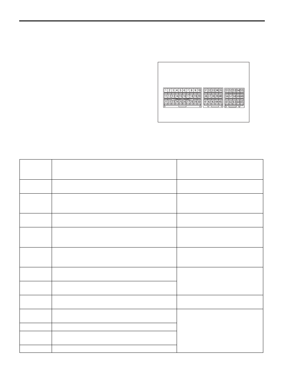
SRS-ECU connector
Side impact sensor
4. Never attempt to repair the wiring harness
connectors of the SRS. If a defective wiring
harness is found, repair or replace it by
referring to the table follows.
SRS-ECU
terminal
No.
Destination of wiring harness
Measures
1, 2
Instrument panel wiring harness
→ knee air bag
module
Repair or replace the instrument
panel wiring harness.
5, 6
Instrument panel wiring harness
→ clock spring →
driver's air bag module (squib)
Replace the clock spring, or repair or
replace the instrument panel wiring
harness.
7, 8
Instrument panel wiring harness
→ passenger's (front)
air bag module (squib)
Repair or replace the instrument
panel wiring harness.
13
Instrument panel wiring harness
→ hazard indicator
assembly [air bag OFF indicator lamp (passenger’s
side)]
Repair or replace the instrument
panel wiring harness.
15
Instrument panel wiring harness
→ hazard indicator
assembly [air bag ON indicator lamp (passenger’s
side)]
Repair or replace the instrument
panel wiring harness.
17, 27
Instrument panel wiring harness
→ front wiring
harness
→ front impact sensor (LH)
Repair or replace the wiring
harnesses.
18, 28
Instrument panel wiring harness
→ front wiring
harness
→ front impact sensor (RH)
22
Floor wiring harness
→ ETACS-ECU (fuse No. 16)
Repair or replace the floor wiring
harness.
23
Instrument panel wiring harness
→ diagnosis
connector
Repair or replace the instrument
panel wiring harness.
24
Instrument panel wiring harness
→ earth
25,26
Instrument panel wiring harness
→ passenger’s air
bag cut OFF switch
29, 30
Instrument panel wiring harness
→ CAN bus line