Mitsubishi Outlander (2013+). Manual - part 493


  Index      Mitsubishi     Mitsubishi Outlander - service repair manual 2013 year


Search            


Content   ..  491  492  493  494   ..


Mitsubishi Outlander (2013+). Manual - part 493


STEERING COLUMN SHAFT ASSEMBLY

ELECTRIC POWER STEERING (EPS)

37-43

STEERING COLUMN SHAFT ASSEMBLY

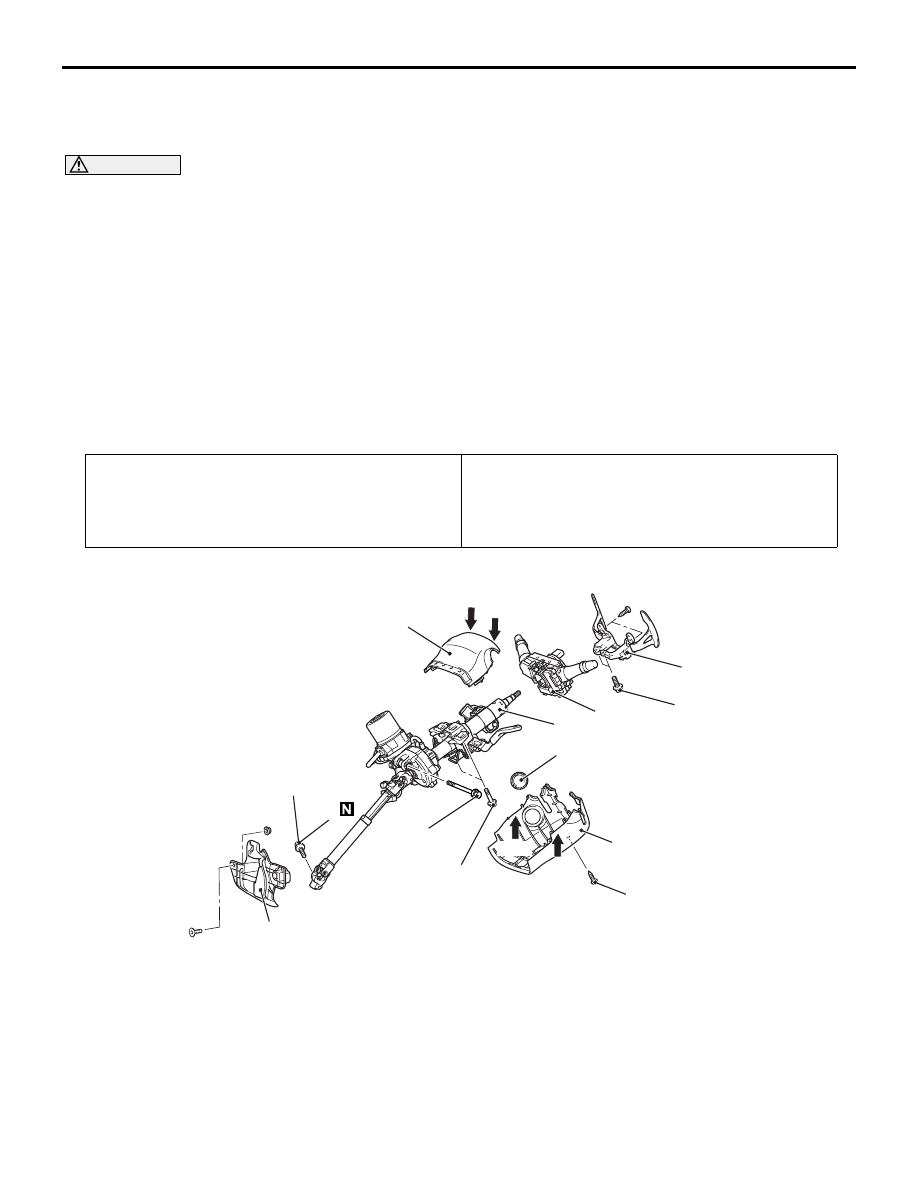
REMOVAL AND INSTALLATION

M1372011501688

CAUTION

• Before removing the steering wheel, driver’s air bag module assembly and knee air bag module 

refer to GROUP 52B 

 Service Precautions , Driver’s Air Bag Module and Clock Spring  and Knee 

Air Bag Module  <Vehicles with knee air bag>.

• After the installation, perform a calibration for the ASC-ECU to learn the steering wheel sensor 

neutral point. (Refer to GROUP 35C 

 On-vehicle Service, Steering Wheel Sensor Calibration ) 

<Vehicles with ASC>. 

• Do not reuse the part that has been dropped because its internal components may be defective 

even if it has no apparent damage.

• Always keep the steering column shaft assembly away from the matter that generates magnetic 

force.

• For the steering column shaft assembly, parts cannot be disassembled.

Pre-removal Operation
• Steering Wheel Straight-ahead Position Check

• Steering Wheel Assembly Removal (Refer to 

P.37-41

).

• Knee Air Bag Module Removal (Refer to GROUP 52B − 

Knee Air Bag Module ) <Vehicles with knee air bag>.

Post-installation Operation
• Knee Air Bag Module Installation (Refer to GROUP 52B − 

Knee Air Bag Module ) <Vehicles with knee air bag>.

• Steering Wheel Assembly Installation (Refer to 

P.37-41

).

• Steering Wheel Straight-ahead Position Check

ACB05462 AB

4

8

3

2

6

1

7

2.5 ± 0.5 N·m

21 ± 3 N·m

36 ± 6 N·m

5

54 ± 11 N·m

4.0 ± 2.0 N·m

Claw

Claw

Claw

Claw

Removal steps 

1.

Ignition key cover <vehicles 
with KOS>

2.

Steering column lower cover

3.

Steering column upper cover

4.

Paddle shift assembly 
<Vehicles with paddle shift>

5.

Column switch assembly 
(Refer to GROUP 54A 

− 

Column Switch )

6.

Steering shaft cover

>>

B

<<

7.

Steering column bolt (Steering 
column shaft assembly and 
steering gear & linkage 
connection) 

EPS-ECU bracket (Refer to 

P.37-51

)

<<

A

>>

>>

A

<<

8.

Steering column shaft 
assembly

Be careful when removing and installing the steering column shaft assembly, because it is heavy.

Removal steps (Continued)

STEERING COLUMN SHAFT ASSEMBLY

ELECTRIC POWER STEERING (EPS)

37-44

REMOVAL SERVICE POINT

<<A>> STEERING COLUMN SHAFT 
ASSEMBLY REMOVAL

1. Ensure that the tilt lever is in the lock position.

2. Remove the steering column shaft assembly 

mounting bolt.

AC904921

Jacket assembly

AC

Motor

One-way 
capsule

CAUTION

• Hold the motor shown because improper 

installation may result when the jacket 
assembly comes off or turns.

• Do not apply any load to the harness because 

an open circuit may occur.

• Do not release the tilt lever because the jacket 

assembly may come off.

• Do not subject separation capsule to any 

shocks because the collision energy absorb-
ing mechanism may not work normally or the 
steering column shaft may fall down after 
installing.

3. Remove the steering column shaft assembly.

INSTALLATION SERVICE POINTS

>>A<< STEERING COLUMN SHAFT 
ASSEMBLY INSTALLATION

1. Ensure that the tilt lever is in the lock position.

AC904921

Jacket assembly

AC

Motor

One-way 
capsule

CAUTION

• Hold the motor shown because improper 

installation may result when the jacket 
assembly comes off or turns.

• Do not apply any load to the harness because 

an open circuit may occur.

• Do not release the tilt lever until the steering 

column shaft assembly is installed to the 
vehicle, because the mounting position to the 
vehicle may be misaligned or the installation 
to the vehicle may become difficult.

• Do not subject the separation capsule to any 

shocks because the collision energy absorb-
ing mechanism may not work normally or the 
steering column shaft may fall down after 
installing. 

• Connect the motor harness to EPS-ECU with-

out excessive bend or twisting.

ACA00173

b

a

c

AC

Tilt lever

2. Hand-tighten the mounting bolts in the order of a, 

b, c, and tighten them in the order of c, b, a to the 
specified torque.

Tightening torque:

• Mounting bolt a: 54 ± 11 Nm

• Mounting bolt b, c: 21 ± 3 Nm

STEERING COLUMN SHAFT ASSEMBLY

ELECTRIC POWER STEERING (EPS)

37-45

>>B<< STEERING COLUMN BOLT 
(STEERING COLUMN SHAFT ASSEMBLY 
AND STEERING GEAR & LINKAGE 
CONNECTION) INSTALLATION

ACA00158 AB

Yoke steering 
column assembly

Bolt hole
(Tapped hole)

Bolt hole
(No tapped hole)

Steering
column bolt

Steering
column bolt

Insert the steering column bolt into the non-threaded 
bolt hole, and tighten it to the specified torque.

Tightening torque : 36 

± 6 Nm

INSPECTION

M1372011001531

STEERING COLUMN SHAFT TOTAL 
ROTATION TORQUE CHECK

AC905486

MB990326

Steering column 
shaft

AC

1. Install the nut to the end of the steering column 

shaft. Then use the preload socket (Special tool: 
MB990326) to rotate the shaft at a rate of one turn 
per 4 to 6 seconds, and then measure the total 
rotation torque.

Standard value:

Total rotation torque: 1.77 N

m or less

Torque fluctuation: 0.6 N

m or less

NOTE: Rotate by 180

°

 in left and right directions 

from the neutral position, and measure the total 
rotation torque.

2. When the measured value is not within the 

standard value, replace the steering column shaft 
assembly (Refer to 

P.37-43

)

STEERING COLUMN SHAFT ASSEMBLY

ELECTRIC POWER STEERING (EPS)

37-46

DISASSEMBLY AND REASSEMBLY

M1372011700634

CAUTION

When replacing the electric steering lock, complete the chassis number registration. (Refer to 
GROUP 42B 

 On-vehicle Service, Registration when Replacing OSS-ECU and Electric Steering Lock 

.)

ACA00058AB

N

1

4

6

5

N

3

2

Disassembly steps 

<<

A

>>

>>

A

<<

1.

Steering lock bolt (Lower)

2.

Steering lock bracket and 
steering lock

<<

A

>>

>>

A

<<

3.

Steering lock bolt (Upper)

>>

A

<<

4.

Steering lock bracket

>>

A

<<

5.

Mechanical steering lock 
<Vehicles without 
KOS>/Electric steering lock 
<Vehicle with KOS>

6.

Steering column shaft 
assembly

NOTE: 

.

A steering lock, a steering lock bracket and a 
steering lock bolt are supplied as a single unit. A 
mechanical steering lock assembly (a mechani-
cal steering lock, a steering lock bracket, a steer-
ing lock bolt, a key reminder switch/key ring 

antenna assembly and an ignition switch are 
included.) <vehicles without KOS> or an electric 
steering lock assembly (a electric steering lock, a 
steering lock bracket and a steering lock bolt are 
included.) <vehicles with KOS> is also supplied.

When the steering lock assembly is supplied, the 
steering lock bracket is assembled to the steering 
lock and the steering lock bolt head (upper) is 
broken off.

For removal and installation of key reminder 
switch/key ring antenna and ignition switch, Refer 
to GROUP 54A 

 Ignition Switch Removal and 

Installation .

DISASSEMBLY SERVICE POINT

<<A>> STEERING LOCK BOLT REMOVAL

1. Use a drill to make a hole just deeply enough for 

the tap to stand on the steering lock bolt.


Content   ..  491  492  493  494   ..