Mitsubishi Outlander (2013+). Manual - part 492
AC104739AB
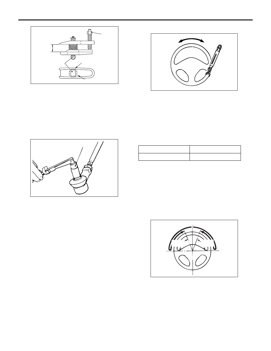
Parallel
Knob
Bolt
Correct
Wrong
ON-VEHICLE SERVICE
ELECTRIC POWER STEERING (EPS)
37-39
2. Turn the bolt and knob to make the special tool
jaws parallel, then hand-tighten the bolt. After
tightening, check that the jaws are still parallel.
NOTE: To adjust the special tool jaws to be paral-
lel, set the knob as shown in the figure so that it
functions as a fulcrum of the jaws.
3. Turn the bolt and disconnect the tie-rod end from
the steering knuckle.
ACX01129 AC
MB990326
4. Operate the ball joint stud to the right and to the
left five times respectively, and install the nut to
the stud. Use the special tool preload socket
(MB990326) to measure the rotation torque of the
ball joint.
Standard value: 0.3
− 3.9 N⋅m
5. If the measurement is greater than the standard
value, replace the tie-rod end (Refer to
).
6. If any looseness or scraping feeling is
experienced in the ball joint, even when the
measurement is within the range of the standard
value, the ball joint should be judged to be faulty.
In this case, replace the tie-rod end (Refer to
STATIONARY STEERING FORCE CHECK
M1372001701205
1. Park the vehicle on a level paved road, position
the steering wheel in the straight ahead direction.
2. Start the engine.
AC000987
3. Position a spring scale on the circumference of
the steering wheel, and measure the steering
force at the time when the steering wheel is
turned clockwise or anticlockwise
±90° from the
neutral position.
At the same time, verify that the steering force
does not vary excessively in both directions.
Standard value:
Steering force
29 N or less
Fluctuation band
5.9 N or less
4. If not within the standard value, check and adjust
the suspected components.
RETURN CHECK OF STEERING WHEEL
M1372001800908
Test-drive the vehicle, and check the following items:
1. Make a gentle or a sharp turn, and check that the
steering force and returning performance do not
differ in right and left wheels by the operator's
feeling.
AC609395
AC
70˚
or more
70˚
or more
2. Turn the steering wheel at a 90
° angle and keep it
for a few seconds while driving at about 35 km/h
speed and then check that the steering wheel
returns more than 70
° when taking hand off.