Mitsubishi Outlander (2013+). Manual - part 435
ON-VEHICLE SERVICE
BASIC BRAKE
35A-7
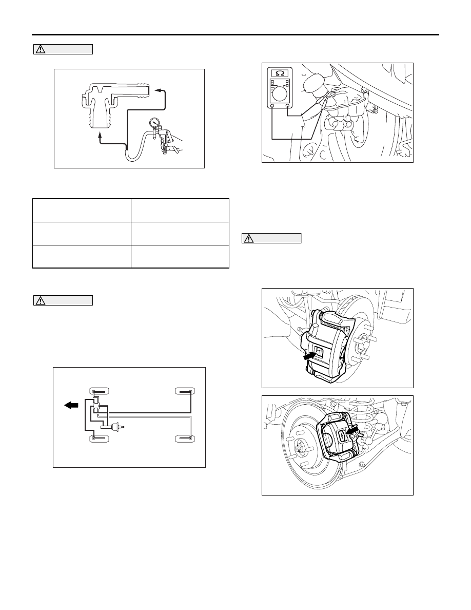
CAUTION
Replace the check valve when it is faulty.
ACC00529
Intake
manifold
side
Booster side
(1)
(2)
AB
2. Using a vacuum pump, check operation of the
check valve.
Vacuum pump
connection
Normal condition
When connected to the
booster side (1)
Vacuum is generated
and maintained.
When connected to the
engine side (2)
No vacuum is generated.
BLEEDING
M1351001401362
CAUTION
Be sure to use the specified brand and type of
brake fluid. Avoid mixing with other type of brake
fluid.
Brake fluid: DOT3 or DOT4
BLEEDING OF BRAKE PIPELINE
AC607427AD
Front of
vehicle
3
4
1
2
1. Perform the bleeding in the order shown in the
figure.
BRAKE FLUID LEVEL SWITCH CHECK
M1351009100986
AC505508AB
The brake fluid level switch is normal when the fol-
lowing conditions are met: When the brake fluid level
is above "MIN," continuity is detected; and when the
level is below "MIN," no continuity is detected.
BRAKE PAD CHECK
M1351017300703
CAUTION
If there is a significant difference in thickness
between the brake pads at right and left, check
the sliding area and the run-out of the brake disc
(Refer to
ACB05917
<Front>
AB
ACB05918
<Rear>
AB
1. Visually check the thickness of brake pad from the
inspection hole of the caliper body.
Standard value: 10.0 mm <Front>, 9.0 mm
<Rear>
Limit: 2.0 mm <Front>, 1.5 mm <Rear>
2. If the brake pad thickness is less than the limit
value, replace the brake pad (Refer to