Mitsubishi Outlander (2013+). Manual - part 419


  Index      Mitsubishi     Mitsubishi Outlander - service repair manual 2013 year


Search            


Content   ..  417  418  419  420   ..


Mitsubishi Outlander (2013+). Manual - part 419


TROUBLESHOOTING

ELECTRONICALLY CONTROLLED 4WD

27C-46

THE SYSTEM IS NORMAL.
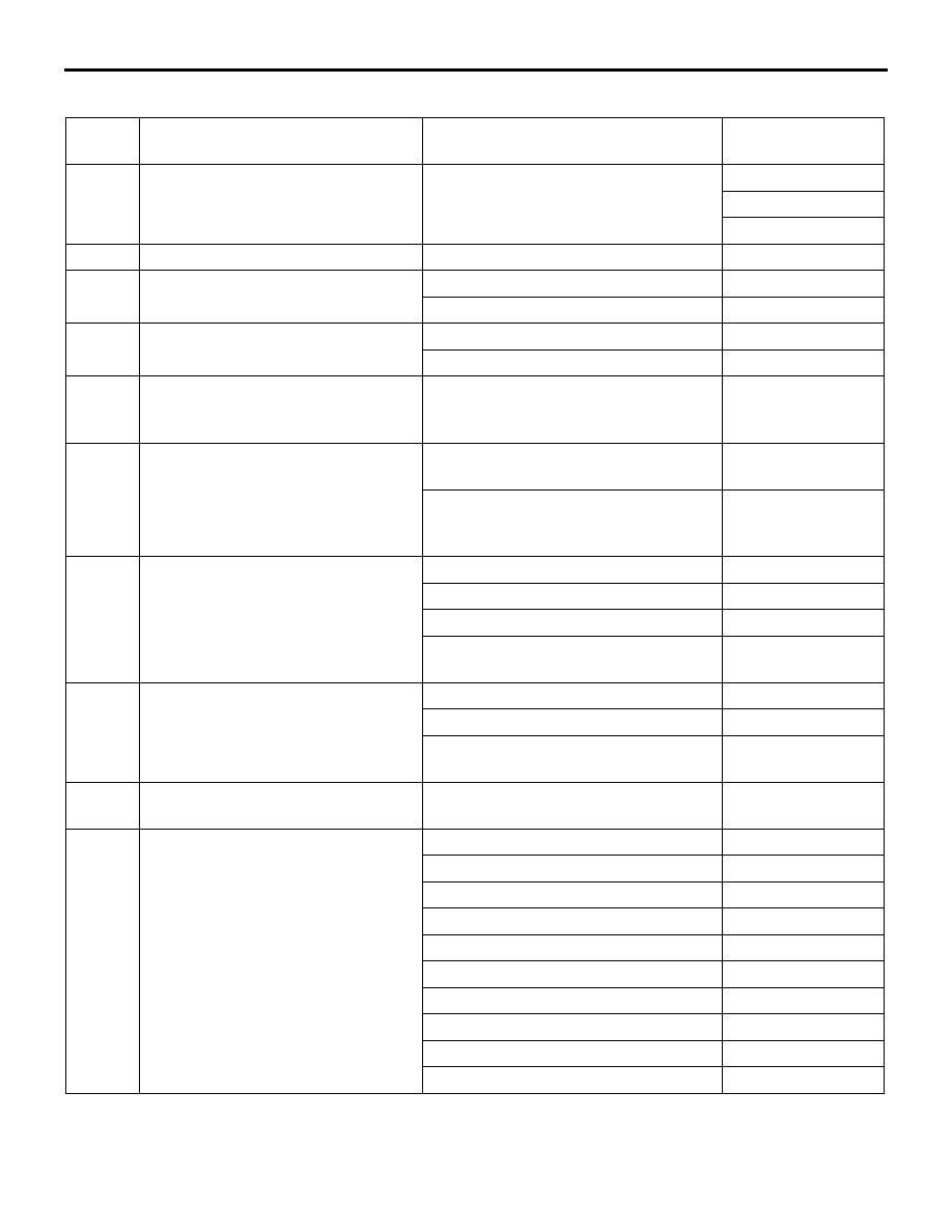
Item 
No.

Display on M.U.T.-III

Check conditions

Normal condition

1

AWC control mode (4WD control 
mode)

4WD is selected (displayed on multi 
information display).

4WD ECO

4WD AUTO

4WD LOCK

5

Centre coupling current

Perform a test run of the vehicle.

− 3 A

6

AWC protection control (4WD 
protection control)

Correct

OFF

Malfunction

ON

7

AWC system fail (4WD system fail)

Correct

OFF

Malfunction

ON

8

Steering angle sensor

Steering wheel steered

Within a 
predetermined 
steering angle

9

Steering angle speed

Steering wheel: Without steering 
wheel operation

0 deg/s

Steering wheel: With steering wheel 
operation

Changes depending 
on the turning 
speed.

10

Steering angle sensor (status)

Normal

Correct

Faulty

Malfunction

Neutral point not learned

Neutral not learned

Neutral point not learned or failed

Neutral not learned 
and Malfunction

11

Accelerator position

Release the accelerator pedal

Approximately 0%

Depress the accelerator pedal

− 100%

Accelerator pedal fully opened

Approximately 
100%

12

Engine speed

Idling and test run

− Maximum 

engine speed

13

A/T gear position

Gear range: P

P

Gear range: R

R

Gear range: N

N

Gear range: 1st

1st

Gear range: 2nd

2nd

Gear range: 3rd

3rd

Gear range: 4th

4th

Gear range: 5th

5th

Gear range: 6th

6th

Gear range: 7th

7th

TROUBLESHOOTING

ELECTRONICALLY CONTROLLED 4WD

27C-47

14

FL wheel speed (raw value)

− (reference because of r/min)

15

FR wheel speed (raw value)

16

RL wheel speed (raw value)

17

RR wheel speed (raw value)

18

FL wheel speed sensor

Perform a test run of the vehicle.

Nearly the same as 
the speedometer 
display

19

FR wheel speed sensor

20

RL wheel speed sensor

21

RR wheel speed sensor

22

Yaw rate sensor

When the vehicle is stationary

Approximately 0 
deg/s

Perform a test run of the vehicle.

−90 − 90 deg/s

23

Lateral G sensor

Vehicle is stopped (horizontal state).

Approximately 0 

m/s

2

Perform a test run of the vehicle.

−10.24 − 10.08 m/s

2

24

Longitudinal G sensor

Vehicle is stopped (horizontal state).

Approximately 0 

m/s

2

Perform a test run of the vehicle.

−10.24 − 10.08 m/s

2

28

Brake switch (CAN input)

Brake pedal: Depressed

ON

Brake pedal: Released

OFF

29

Parking brake SW (CAN input)

Parking brake lever: Pulled

ON

Parking brake lever: Released

OFF

30

Ignition SW (CAN input)

Ignition switch: ACC

ACC

Ignition switch: ON

ON

Ignition switch: START

START

31

Battery voltage (CAN input)

Ignition switch: ON

− 17 V

32

IOD fuse (CAN input)

Fuse inserted

ON

Fuse removed

OFF

33

Odometer (CAN input)

Ignition switch: ON

− 1,677,721.4 km

34

Ambient temperature (CAN input)

Ignition switch: ON

-30 

°C − 85 °C

35

Ignition off time (CAN input)

After ignition switch: OFF for one 
minute or more, ignition switch: ON

− 254 min

38

IG1

Ignition switch: ON

ON

Ignition switch: OFF

OFF

39

ECU power supply voltage

Ignition switch: ON

10 

− 18.75 V

40

Output load voltage

Ignition switch: ON

10 

− 18.75 V

41

Mode SW

4WD SW : OFF

OFF

4WD SW : ON

ON

44

SAS (adjusted value)

Ignition switch: ON

−15 − 15 deg

45

Chassis Number writing counter

Ignition switch: ON

Writing count

Item 
No.

Display on M.U.T.-III

Check conditions

Normal condition

TROUBLESHOOTING

ELECTRONICALLY CONTROLLED 4WD

27C-48

SYSTEM SHUT-DOWN

M.U.T.-III display data does not agree with the actual 
data when 4WD-ECU deactivates the 4WD control 
function by the fail-safe function.

SPECIAL FUNCTION

M1274013500011

RESET

Item 
No.

Display on M.U.T.-III

Initialization contents

1

SAS adjusted value

Resets the steering wheel sensor neutral position learned value.

3

Centre coupling estimated temp.

Reset the estimated temperature of centre coupling.

TEST

Item 
No.

Display on M.U.T.-III

Test content

Normal conditions

4

Control OFF

The electronic control coupling 
(centre) operation stops

Refer to the electronic control coupling 
(centre) operation check.

6

Centre coupling 
operation check

Drive the electronic control 
coupling (centre) with control 
current of 3 A.

Maximum 60 seconds

1. The test can be performed only when all the 

following conditions are satisfied.

• Every wheel speed sensor input is 20 km/h or 

less.

• No system malfunction is detected.

• The steering angle of steering wheel is within 

±30° from the neutral position.

2. With the test, when any of the conditions below is 

met, the forced activation will be cancelled.

• Any of the wheel speed sensors detects an input 

of 20 km/h or more (excluding item No. 4 "Control 
OFF").

• A system malfunction is detected.

• The forced activation time has elapsed.

• M.U.T.-III is removed.

• M.U.T.-III clear key is operated.

The sensor neutral position learned value initializa-
tion can be performed only when the vehicle is 
stopped.

CHECK AT ECU TERMINALS

M1274001300139

ACB05609

46

Chassis Number (original) lock

Ignition switch: 
ON

Locked

Lock

Unlocked

Unlock

47

Mileage counter

Ignition switch: ON

Counter value

48

Coding counter

Ignition switch: ON

− 255 times

Item 
No.

Display on M.U.T.-III

Check conditions

Normal condition

Termin
al No.

Termi
nal 
code

Inspection Item

Check condition

Normal condition

1

SOL+

Electronic control 
coupling solenoid 
(centre)

Using M.U.T.-III, perform "Test Item No. 4: 
Control OFF" of "SPECIAL FUNCTION"

1 V or less

Using M.U.T.-III, perform "Test Item No. 6: 
Centre coupling operation check" of 
"SPECIAL FUNCTION"

Approximately 8 V

3

BATT

Power supply

Always

System voltage

4

IG1

Ignition switch

Ignition switch: ON

System voltage

Ignition switch: OFF

1 V or less

5

CANH

CAN-H

9

SOL-

Electronic control 
coupling solenoid 
(centre)

Always

1 V or less

10

GND1

Earth

Always

1 V or less

13

CANL

CAN-L

16

SW-1

4WD switch signal

Ignition switch: ON

4WD switch: ON

System voltage

4WD switch: OFF

1 V or less

ON-VEHICLE SERVICE

ELECTRONICALLY CONTROLLED 4WD

27C-49

ON-VEHICLE SERVICE

CHECK OF ELECTRONIC CONTROL 
COUPLING

M1274005700225

SIMPLE OPERATION CHECK OF ELEC-
TRONIC CONTROL COUPLING

CAUTION

The following checks in the 4WD mode must be 
completed within one minute in total to protect 
the 4WD drive system components and parking 
brake.
1. Raise the vehicle.

ACB05570 AB

Marking

2. Mark the front and rear tyres for easy 

identification of tyre rotation.

3. Adjust the parking brake lever to the normal 

conditions. (Refer to GROUP 36 

− On-vehicle 

Service, Parking Brake Lever Stroke Check and 
Adjustment ).

4. Pull the parking brake lever by two notches. Then 

start the engine.

NOTE: Activating the parking brake slightly pre-
vents the drive force transferring to the rear 
wheels by a friction in the electronic control cou-
pling. If the following 2WD mode is checked with-
out the parking brake activation, the drive force is 
transferred to the rear wheels by a friction in the 
electronic control coupling.

5. Execute the special test (item No. 4: control off) 

(Refer to 

P.27C-48

) to switch the drive mode into 

2WD forcibly.

6. Move the shift lever into the selector lever into D 

position.

7. Depress the accelerator pedal gradually, and 

maintain the vehicle speed at approximately 10 
km/h. (Make sure that the rear wheels do not 
rotate).

8. Stop the engine.

9. Start the engine again, and move the shift lever 

into the selector lever into D position.


Content   ..  417  418  419  420   ..