Mitsubishi Outlander (2013+). Manual - part 420


  Index      Mitsubishi     Mitsubishi Outlander - service repair manual 2013 year


Search            


Content   ..  418  419  420  421   ..


Mitsubishi Outlander (2013+). Manual - part 420


ON-VEHICLE SERVICE

ELECTRONICALLY CONTROLLED 4WD

27C-50

10.Depress the accelerator pedal gradually, and 

maintain the vehicle speed at approximately 10 
km/h.

11.Switch the 4WD switch to "4WD AUTO" position, 

and check that the rear wheels are rotating.

After the above checks are completed, if the rear 
wheel rotation satisfies the above conditions, it is 
judged that the electronic control coupling operates 
correctly. If the rear wheel rotation does not satisfy 
the above conditions, replace the electronic control 
coupling. (Refer to 

P.27C-53

.)

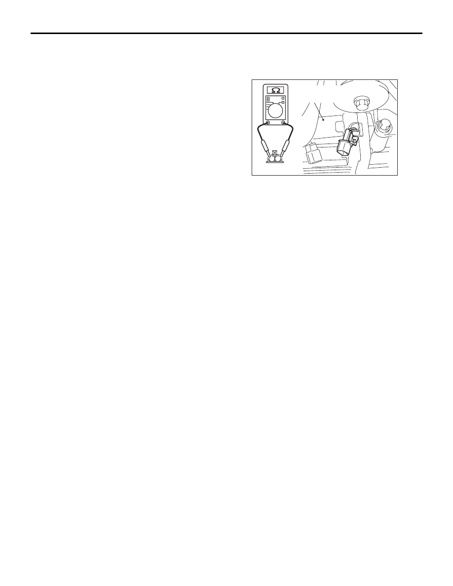
RESISTANCE MEASUREMENT BETWEEN 
ELECTRONIC CONTROL COUPLING 
SOLENOID CONNECTOR TERMINALS

AC707679

2

1

AC

D-113-1

Electronic
control coupling

Disconnect the electronic control coupling solenoid 
connector, and measure the resistance value 
between the connector terminals on the unit side. If 
the measured resistance value is out of the standard 
value range, replace the electronic control coupling. 
(Refer to 

P.27C-53

.)

Standard value: 2.2 

 4.0 

4WD-ECU

ELECTRONICALLY CONTROLLED 4WD

27C-51

4WD-ECU

REMOVAL AND INSTALLATION

M1274001600141

Pre-removal and post-installation operation
Removal and installation of the bottom cover assembly and 
glove box (Refer to GROUP 52A 

− Instrument Panel 

Assembly .)

ACB04915 AB

11 ± 4 N·m

1

2

Removal steps 

1.

4WD-ECU

2.

4WD-ECU bracket

4WD SWITCH

ELECTRONICALLY CONTROLLED 4WD

27C-52

4WD SWITCH

REMOVAL AND INSTALLATION

M1274009800019

ACB04916 AB

1

4

3

2

2.5 ± 0.5 N·m

Removal steps 

1.

Front floor console panel (Refer to 
GROUP 52A Front Floor Console 
Assembly )

2.

Connector connection

3.

Bezel

4.

4WD switch

4WD SWITCH CHECK

M1274009900016

ACB04917AB

Item

When the 4WD 
switch is 
released (Not 
being operated)

When the 4WD 
switch is 
pressed

Continuity 
between 
terminal No. 2 
and No. 6

No continuity

Continuity exists 
(2 

Ω or less)

Continuity 
between 
terminal No. 3 
and No. 10

Continuity exists Continuity exists

ELECTRONIC CONTROL COUPLING

ELECTRONICALLY CONTROLLED 4WD

27C-53

ELECTRONIC CONTROL COUPLING

REMOVAL AND INSTALLATION

M1274002100150

ACB04914

54 ± 5 N·m

1

3

48 ± 6 N·m

4

6

AB

7.9 ± 0.9 N·m

7

5

Differential
side

Electronic control
coupling side

Semi-drying sealant: 
ThreeBond 1215, 1216, 1217 or 
equivalent

2

4

Removal steps 

1.

Propeller shaft assembly (Refer to 
GROUP 25 

− Propeller Shaft ).

2.

Cover

3.

Breather hose connection

4.

Connector connection

5.

Bracket

>>

A

<<

6.

Electronic control coupling

7.

Wave washer

INSTALLATION SERVICE POINT

>>A<< ELECTRONIC CONTROL COU-
PLING INSTALLATION

ACB06011AB

A

Electronic control
coupling

1. Check that the length of the electronic control 

coupling stud bolt (A) is within the standard value 
range.

Standard value: 21.6 

 24.4 mm

2. If it exceeds either of the limits, clean the threads 

for the electronic control coupling and replace the 
stud bolt.

Tightening torque: 13 

± 2 Nm


Content   ..  418  419  420  421   ..